Suzuki Grand Vitara JB416 / JB420 / JB419. Service manual - part 502
 

  Index      Suzuki     Suzuki Grand Vitara JB416 / JB420 / JB419 - service and repair manual 2007 year


Search            copyright infringement  


Content   ..  500  501  502  503   ..


Suzuki Grand Vitara JB416 / JB420 / JB419. Service manual - part 502


9E-19 Glass / Windows / Mirrors: 

Rear End Door Window Defogger Relay 
Inspection

S6JB0A9506013

1) Disconnect negative (–) cable from battery.
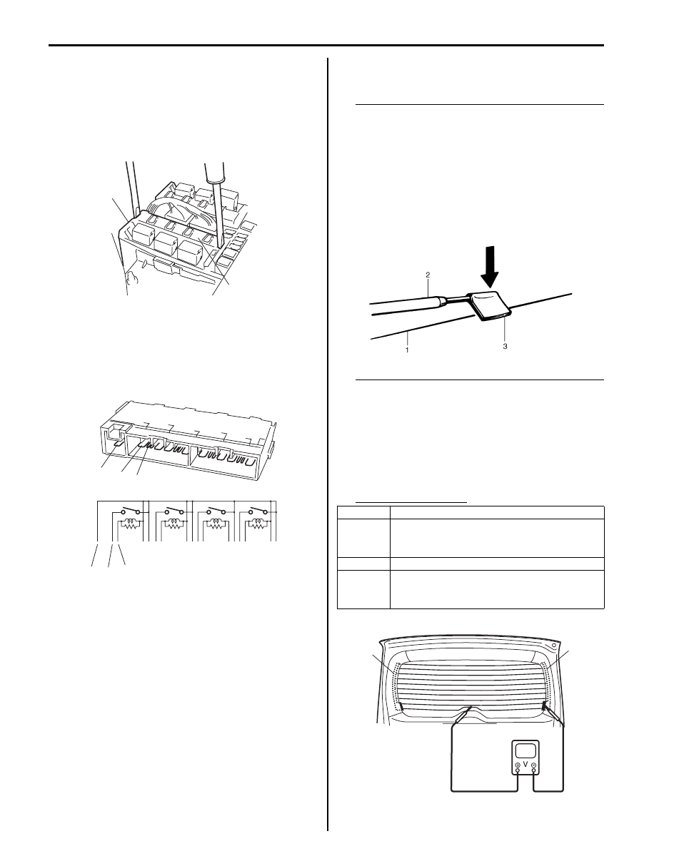
2) Remove rear end door window defogger relay 

(included in integration relay) (1) from main fuse box 
(2).

3) Check that there is no continuity between terminal 

“a” and “b”. If there is continuity, replace relay.

4) Check that there is continuity between terminals “a” 

and “b” when a 12 V battery is connected to 
terminals “a” and “c”.
If malfunction is found, replace it with a new one.

Rear End Door Window Defogger Wire 
Inspection

S6JB0A9506014

NOTE

• When cleaning rear end door window 

glass, use a dry cloth to wipe it along heat 
wire (1) direction.

• When cleaning glass, do not use detergent 

or abrasive-containing glass cleaner.

• When measuring wire voltage, use a tester 

with positive probe (2) wrapped with a tin 
foil (3) which should be held down on wire 
by finger pressure.


Wire Damage Inspection

1) Start engine.
2) Turn on defogger switch.
3) Measure voltage at the center of each defogger wire 

(1), and check defogger wire condition according to 
the following table.
If defogger wire open is found, go to next step.

Defogger wire voltage

2

1

I5JB0A950031-01

“c”

“b”

“a”

“b”

“a”

“c”

I5JB0A950032-02

Voltage

Circuit

0 – 1 V Defogger wire open between its center 

and defogger wire power source terminal 
end (2)

4 – 6 V Normal condition

10 – 12 V Defogger wire open between its center 

and defogger wire ground terminal end 
(3)

I2RH01950002-01

2

1

I5JB0A950033-01

Glass / Windows / Mirrors:  9E-20

4) Touch voltmeter negative (–) lead to defogger wire 

ground terminal end (1).

5) Touch voltmeter positive (+) lead with a foil strip to 

defogger wire power source terminal end (2), then 
move it along wire to defogger wire ground terminal 
end (1).
The place where voltmeter fluctuates from 10 – 12 V 
to 0 – 1 V is where there is open.
If found defective, repair defogger wire referring to 
“Rear End Door Window Defogger Wire Repair”.

Rear End Door Window Defogger Wire Repair

S6JB0A9506015

1) Use white gasoline for cleaning.
2) Apply masking tape (1) at both upper and lower 

sides of heat wire (2) to be repaired.

3) Apply commercially-available repair agent (3) with a 

fine-tip brush (4).

4) 2 to 3 minutes later, remove masking tapes (1).

5) Leave repaired heat wire as it is for at least 24 hours 

before operating the defogger again.

Power Window Main Switch Inspection

S6JB0A9506016

Switch for driver side window 

1) Remove driver side door trim referring to step 1) to 

3) of “Front Door Glass Removal and Installation”.

2) Remove power window main switch from door trim.

3) Connect 12 V battery positive (+) terminal to terminal 

“IG” of power window main switch and its negative (–
) terminal to terminal “E” of power window main 
switch.

4) Check for continuity between terminals as shown 

below.
If check result is not as specified, replace power 
window main switch.

2

1

I5JB0A950034-01

I2RH01950005-01

[A]: LH steering vehicle
[B]: RH steering vehicle

I5JB0A950035-03

9E-21 Glass / Windows / Mirrors: 

Switch for other window than driver side

1) Remove driver side door trim referring to step 1) to 

3) of “Front Door Glass Removal and Installation”.

2) Remove power window main switch from door trim.
3) Check for continuity between terminals as shown 

below.

If check result is not as specified, replace power window 
main switch.

Power Window Sub Switch Inspection

S6JB0A9506017

1) Remove front and/or rear door trim from door panel, 

refer to Step 1) to 3) of “Front Door Glass Removal 
and Installation” an
d/or “Rear Door Glass Removal 
and Installation”.

2) Remove power window sub switch from door trim.
3) Check for continuity between terminals at each 

switch condition.

If check result is not as specified, replace switch.

[A]: LH steering vehicle
[B]: RH steering vehicle

I5JB0A950036-02

I5JB0A950037-01

Glass / Windows / Mirrors:  9E-22

Door Mirror Components

S6JB0A9506018

Door Mirror Removal and Installation

S6JB0A9506019

When removing or installing door mirror, refer to the 
figure in “Door Mirror Components”.

Power Door Mirror Switch Inspection

S6JB0A9506020

1) Remove driver side door trim referring to step 1) to 

3) of “Front Door Glass Removal and Installation”.

2) Remove power window main switch from door trim.
3) Check for continuity between terminals at each 

switch position.
If check result is not as specified, replace door mirror 
switch.

“1”

“3”

“2”

1

2,

2,

2,

I5JB0A950038-02

1. Door mirror
2. Door mirror mounting nut

:Tighten nuts in such order as indicated in the figure.

A

B

C

D

E

F

G

Up

Down

Left

Right

L

R

A

B

C

D

E

F

G

I5JB0A950039-01


Content   ..  500  501  502  503   ..