Suzuki Grand Vitara JB416 / JB420 / JB419. Service manual - part 493
 

  Index      Suzuki     Suzuki Grand Vitara JB416 / JB420 / JB419 - service and repair manual 2007 year


Search            copyright infringement  


Content   ..  491  492  493  494   ..


Suzuki Grand Vitara JB416 / JB420 / JB419. Service manual - part 493


9C-24 Instrumentation / Driver Info. / Horn: 

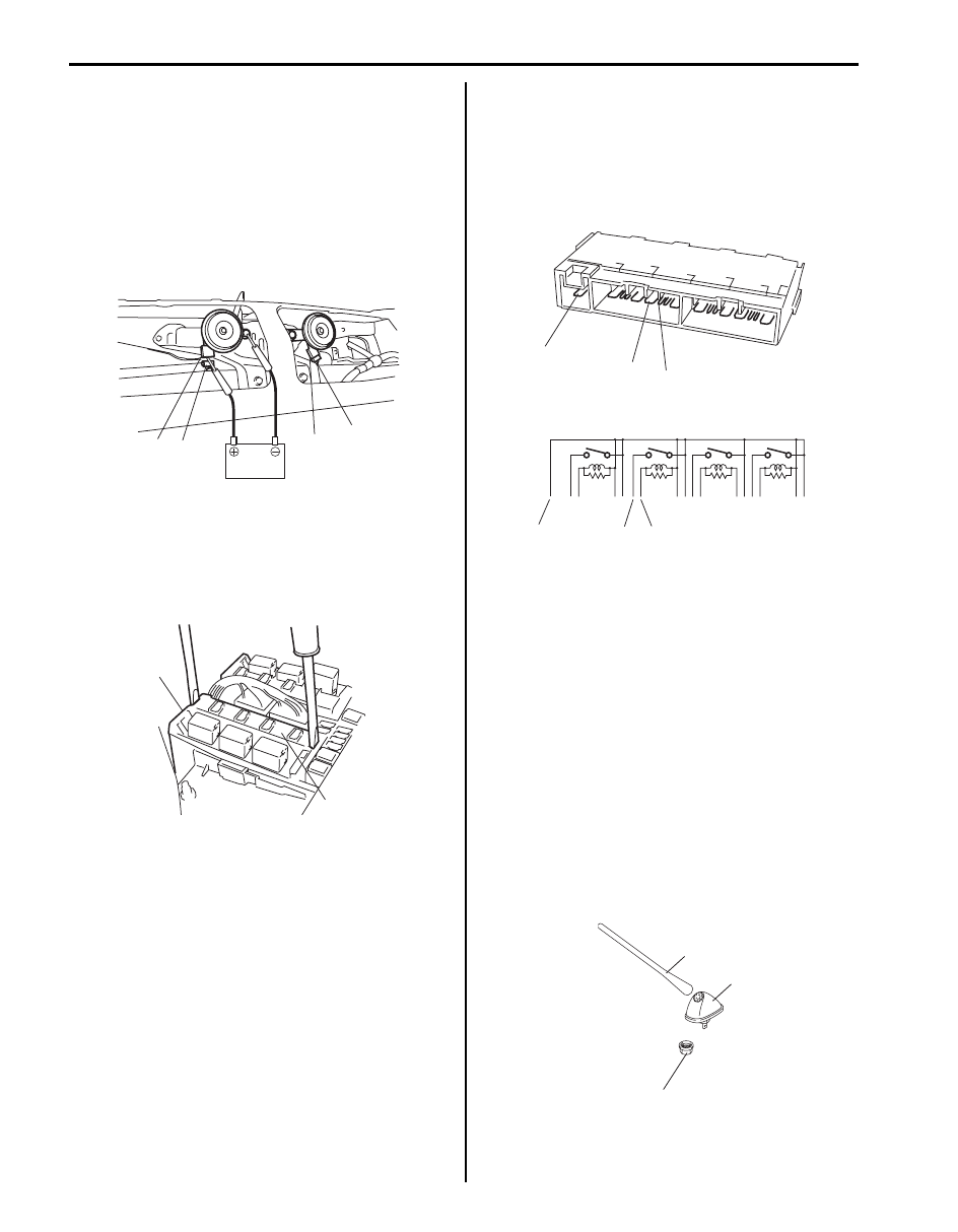
Horn Inspection

S6JB0A9306022

1) Disconnect negative (–) cable at battery.
2) Remove front bumper referring to “Front Bumper 

Components in Section 9K”. 

3) Disconnect horn connector (1).
4) Connect battery positive (+) to terminal of horn 

connector (2) and negative (–) terminal to body 
ground.
If horn is not sounding, replace horn.

Horn Relay Inspection

S6JB0A9306023

1) Disconnect negative (–) cable at battery.
2) Remove horn relay (included in integration relay) (1) 

from main fuse box (2).

3) Check that there is no continuity between terminal 

“a” and “b”. 
If there is continuity, replace relay.

4) Check that there is continuity between terminals “a” 

and “b” when a 12 V battery is connected to terminal 
“a” and “c”. 
If malfunction is found, replace integration relay.

Antenna Base Removal and Installation

S6JB0A9306024

Removal

1) Remove antenna (1) from antenna base (2).
2) Remove head lining referring to “Head Lining 

Removal and Installation in Section 9H”.

3) Disconnect antenna feeder (3) from antenna base 

(2).

4) Remove antenna base (2) from vehicle.

Installation
Reverse removal procedure noting the following.
• Tighten antenna base mounting nut to specified 

torque.

Tightening torque
Antenna base mounting nut (a):  10 N·m (1.0 kgf-
m, 7.5 lb-ft)

1

2

2

1

I5JB0A930024-01

2

1

I5JB0A950031-01

“b”

“c”

“a”

“b”

“c”

“a”

I5JB0A930025-03

(a)

1

2

I4RH01930009-01

Instrumentation / Driver Info. / Horn:  9C-25

Remote Audio Control Switch Removal and 
Installation (If Equipped)

S6JB0A9306025

Removal

1) Remove steering wheel referring to “Steering Wheel 

Removal and Installation in Section 6B”.

2) Remove steering wheel cover (1) from steering 

wheel.

3) Remove remote audio control switch (1) with cruise 

control switch (3) (if equipped).

Installation
Reverse removal procedure for installation.

Remote Audio Control Switch Inspection (If 
Equipped)

S6JB0A9306026

1) Remove driver air bag (inflator) module referring to 

“Driver Air Bag (Inflator) Module Removal and 
Installation in Section 8B”.

2) Disconnect remote audio control switch connector 

from contact coil.

3) Check switch for resistance between “a” and “b” 

terminals under each condition below.
If check result is not satisfactory, replace remote 
audio control switch.

Remote audio control switch resistance
All switches released (OFF): 5119 – 5223 k

“ENTER” switch (1) pushing on (ON): 55 – 57 

“+” switch (2) pushing on (ON): 129 – 133 

“–” switch (3) pushing on (ON): 238 – 244 

“MODE” switch (4) pushing on (ON): 416 – 426 


 switch (5) pushing on (ON): 743 – 759 


 switch (6) pushing on (ON): 1555 – 1587 

Vehicle Speed Signal Inspection (For Audio 
Unit) (If Equipped)

S6JB0A9306027

Check vehicle speed pulse output signal of BCM 
referring to “Reference waveform No.5” under 
“Inspection of BCM and Its Circuits in Section 10B”.

2. screw

1

I5JB0A930026-04

1

2

2

3

I5JB0A930027-01

[A]: Without cruise control system
[B]: With cruise control system

5

6

4

1

2

3

[A]

[B]

“b”

“a”

“b”

“a”

I6JB01930012-02

9C-26 Instrumentation / Driver Info. / Horn: 

Specifications

Tightening Torque Specifications

S6JB0A9307001

NOTE
The specified tightening torque is also described in the following.
“Audio System Component Location”


Reference:
For the tightening torque of fastener not specified in this section, refer to “Fastener Information in Section 0A”.

Fastening part

Tightening torque

Note

N

m

kgf-m

lb-ft

Instrument panel mounting bolt

23

2.3 

17.0

)

Lower anchor bolt

35

3.5 

25.5

)

Antenna base mounting nut

10

1.0 

7.5

)

Wipers / Washers:  9D-1

Body, Cab and Accessories

Wipers / Washers

Diagnostic Information and Procedures

Front Wiper and Washer Symptom Diagnosis

S6JB0A9404001

Rear Wiper and Washer Symptom Diagnosis

S6JB0A9404002

Condition

Possible cause

Correction / Reference Item

Wiper malfunctions

Circuit fuse blown

Replace fuse and check for short circuit.

Wiper motor faulty

Check wiper motor referring to “Windshield 
Wiper Motor Inspection”.

Combination switch (wiper switch) faulty Check wiper switch referring to “Windshield 

Wiper and Washer Switch Inspection”.

Wiring or grounding faulty

Repair circuit.

Washer malfunctions

Washer hose or nozzle clogged

Clean or repair clogged hose or nozzle.

Circuit fuse blown

Replace fuse and check for short circuit.

Washer motor faulty

Check washer motor referring to “Washer 
Pump Inspection”
.

Combination switch (washer switch) 
faulty

Check washer switch referring to “Windshield 
Wiper and Washer Switch Inspection”.

Wiring or grounding faulty

Repair circuit.

Condition

Possible cause

Correction / Reference Item

Wiper malfunctions

NOTE

• Use of SUZUKI scan 

tool makes it easy to 
check whether a faulty 
condition is on the 
input side or output 
side of BCM. For 
checking procedure, 
refer to “Diagnosis 
Using Output Test 
Function of SUZUKI 
Scan Tool” under 
“Scan Tool Data in 
Section 10B”.

• Check each part in the 

order from the top of 
the following list.


Circuit fuse blown

Replace fuse and check for short circuit.

Wiper motor faulty

Check wiper motor referring to “Rear Wiper 
Motor Inspection”.

Combination switch (wiper switch) faulty Check wiper switch referring to “Rear Wiper 

and Washer Switch Inspection”.

Rear wiper relay faulty

Check rear wiper relay referring to “Rear Wiper 
Relay Inspection”.

Wiring or grounding faulty

Repair circuit.

BCM faulty

Replace after making sure that none of above 
parts is faulty.

Washer malfunctions

Washer hose or nozzle clogged

Clean or repair clogged hose or nozzle.

Circuit fuse blown

Replace fuse and check for short circuit.

Washer motor faulty

Check washer motor referring to “Washer 
Pump Inspection”
.

Combination switch (washer switch) 
faulty

Check washer switch referring to “Rear Wiper 
and Washer Switch Inspection”
.

Wiring or grounding faulty

Repair circuit.


Content   ..  491  492  493  494   ..