Suzuki Grand Vitara JB416 / JB420 / JB419. Service manual - part 492
 

  Index      Suzuki     Suzuki Grand Vitara JB416 / JB420 / JB419 - service and repair manual 2007 year


Search            copyright infringement  


Content   ..  490  491  492  493   ..


Suzuki Grand Vitara JB416 / JB420 / JB419. Service manual - part 492


9C-20 Instrumentation / Driver Info. / Horn: 

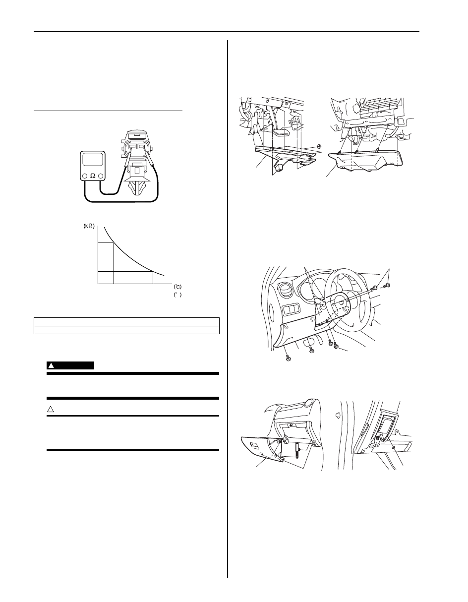
Outside Air Temperature Sensor Inspection (If 
Equipped)

S6JB0A9306013

Measure resistance of outside air temperature sensor 
using an ohmmeter.
If resistance is out of specification, replace outside air 
temperature sensor.

Outside air temperature sensor resistance
1.62 k

 – 1.78 k at 25 °C (77 °F)

Instrument Panel Removal and Installation

S6JB0A9306014

WARNING

!


Refer to “Air Bag Warning in Section 00” 
before starting service work.


CAUTION

!


Position heat control mode into FOOT MODE 
before removing instrument panel to avoid 
the damage to air flow control door.


Removal

1) Disconnect negative cable at battery.
2) Remove driver side instrument panel under cover (1) 

and passenger side instrument panel under cover 
(2).

3) Disable air bag system referring to “Disabling Air 

Bag System in Section 8B”.

4) Remove steering column hole cover (1).
5) Turn steering wheel to remove steering column 

cover screws (3).

6) Remove steering column covers (2).

7) Remove glove box (1).
8) Remove hood latch release lever (2).

“A”: Resistance
“B”: Temperature

“B”

“A”

5.50

1.70

0

32

25
77

F

I4RS0A930017-01

1

2

I5JB0A930011-02

1

2

3

3

I5JB0A940020-02

1

2

I5JB0A930012-02

Instrumentation / Driver Info. / Horn:  9C-21

9) Remove console box referring to “Console Box 

Components in Section 9H”.

10) Remove front pillar trims (1) front side sill scuffs (2) 

and dash side trims (3).

11) Disconnect instrument panel harness connectors, 

inside air temperature sensor duct and antenna 
cable instrument panel removal.

12) Remove steering column mounting referring to 

“Steering Column Assembly Removal and 
Installation in Section 6B”.

13) Remove instrument panel ground wire.
14) Remove instrument panel mounting bolts (1).
15) Remove instrument panel (2) with steering support 

member and instrument panel harness.

Installation
Reverse removal procedure noting the following.
• When installing each part, be careful not to catch any 

cable or wiring harness.

• Tighten instrument panel mounting bolts to specified 

torque

Tightening torque
Instrument panel mounting bolt (a):  23 N·m (2.3 
kgf-m, 17.0 lb-ft)

• Tighten steering column mounting nuts referring to 

“Steering Column Assembly Removal and Installation 
in Section 6B”.

• Enable air bag system referring to “Enabling Air Bag 

System in Section 8B”.

Information Display (Clock) Removal and 
Installation

S6JB0A9306015

Removal

1) Remove audio unit referring to “Audio Unit Removal 

and Installation”.

2) Remove center ventilation louver (1) from instrument 

panel (2) pulling it arrow direction as shown.

3) Disconnect hazard switch connector.

4) Remove information display (clock) (1) from 

instrument panel (2) pulling it in arrow direction 
shown in figure.

5) Disconnect information display (clock) coupler.

Installation
Reverse removal procedure.

2

3

1

I5JB0A930013-02

(a)

(a)

I5JB0A930015-01

3. screw

1

2

3

I5JB0A930016-01

1

2

I5JB0A930017-01

9C-22 Instrumentation / Driver Info. / Horn: 

Audio Unit Removal and Installation

S6JB0A9306016

Removal

1) Disconnect negative (–) cable at battery.
2) Remove instrument panel center garnish trims (1).

3) Remove 6 mounting screws (1).
4) Disconnect electrical connectors from audio unit and 

HVAC control module.

5) Remove audio unit (2) with HVAC control module 

from instrument panel.

6) Remove audio unit from HVAC control module.

Installation
Reverse removal procedure.

Front Speaker Removal and Installation

S6JB0A9306017

Removal

1) Remove door trim referring to Step 1) to 3) of “Front 

Door Glass Removal and Installation in Section 9E”.

2) Remove 3 front speaker mounting screws (1).
3) Remove front speaker (2) from front door (3).
4) Disconnect front speaker coupler from front speaker 

(2).

Installation
Reverse removal procedure.

Rear Speaker Removal and Installation (5 Door 
Model)

S6JB0A9306018

Removal

1) Remove door trim referring to Step 1) to 3) of “Rear 

Door Glass Removal and Installation in Section 9E”.

2) Remove 3 rear speaker mounting screws (1).
3) Remove rear speaker (2) from rear door (3).
4) Disconnect rear speaker coupler from rear speaker 

(2).

Installation
Reverse removal procedure.

1

I5JB0A930018-03

2

1

I5JB0A930019-04

1

2

3

I4RS0A930027-01

1

2

3

I4RS0A930027-01

Instrumentation / Driver Info. / Horn:  9C-23

Rear Speaker Removal and Installation (3 Door 
Model)

S6JB0A9306019

Removal

1) Remove right and left lower anchor bolts (2) from 

body panel.

2) Remove quarter lower trim (1).

3) Remove 3 rear speaker mounting screws (1) and 

rear speaker (2) from quarter panel.

4) Disconnect rear speaker coupler from rear speaker 

(2).

Installation
Reverse removal procedure noting the following.
• Tighten lower anchor bolts to specified torque.

Tightening torque
Lower anchor bolt (a):  35 N·m (3.5 kgf-m, 25.5 lb-ft)

GPS Antenna Removal and Installation (If 
Equipped)

S6JB0A9306020

Removal

1) Remove center ventilation louver referring to step 1) 

and 2) of “Information Display (Clock) Removal and 
Installation”.

2) Disconnect GPS antenna connector from navigation 

unit referring to “Audio Unit Removal and 
Installation”.

3) Remove GPS antenna (1).

Installation
Reverse removal procedure.

Horn Removal and Installation

S6JB0A9306021

Removal

1) Disconnect negative (–) cable at battery.
2) Remove front bumper referring to “Front Bumper 

Components in Section 9K”.

3) Disconnect horn connector (1).
4) Remove horn (2).

Installation
Reverse removal procedure for installation.

1

2

I5JB0A930020-02

2

1

I5JB0A930021-02

(a)

I5JB0A930022-02

1

I5JB0A930023-01

1

2

2

1

I5JB0A930029-01


Content   ..  490  491  492  493   ..