Suzuki Grand Vitara JB416 / JB420 / JB419. Service manual - part 352
 

  Index      Suzuki     Suzuki Grand Vitara JB416 / JB420 / JB419 - service and repair manual 2007 year


Search            copyright infringement  


Content   ..  350  351  352  353   ..


Suzuki Grand Vitara JB416 / JB420 / JB419. Service manual - part 352


5B-55 Manual Transmission/Transaxle: For Diesel Engine Model

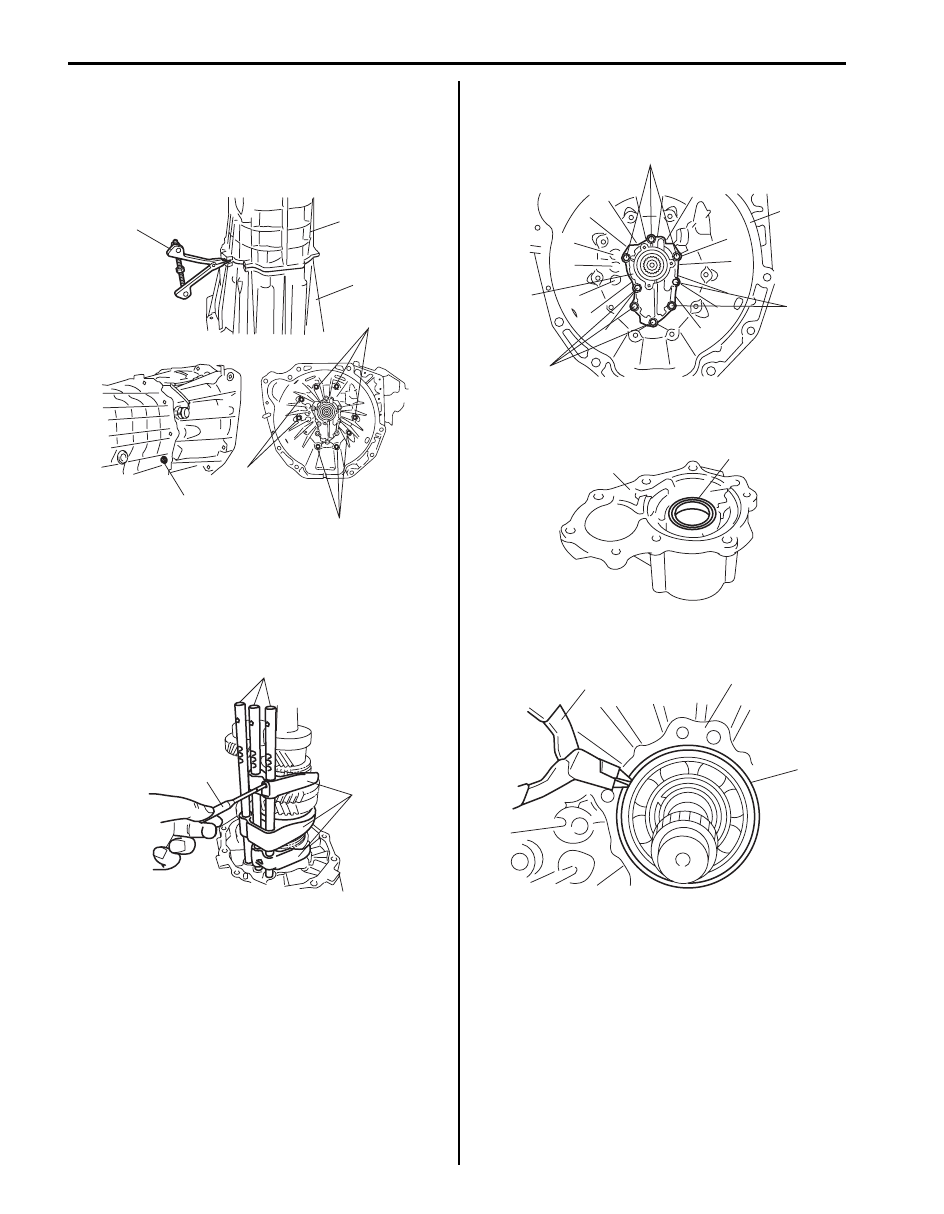
10) Remove rear case to front case bolts (1), then 

separate rear case (2) from front case (3) using 
special tool.

Special tool
(A):  09912–34510

11) Drive out each gear shift shaft pin using special tool 

and then remove each gear shift shaft (1), fork (2), 
ball and inter lock pin.

Special tool
(A):  09922–85811

12) Remove input shaft bearing retainer to front case 

bolt (1), then separate input shaft bearing retainer (2) 
from front case (3).

13) Remove oil seal (1) from input shaft bearing retainer 

(2) using flat end rod or the like, if necessary.

14) Remove input shaft front bearing circlip (1) from front 

case (3) using snap ring pliers (2).

1

2

3

(A)

1

1

1

I5JB0B520030-01

(A)

1

2

I5JB0B520031-01

3

1

1

1

2

I5JB0B520032-01

1

2

I5JB0B520033-01

1

2

3

I5JB0B520034-01

Manual Transmission/Transaxle: For Diesel Engine Model 5B-56

15) Remove input shaft assembly, main shaft assembly 

(1) and countershaft assembly (2) all together from 
front case (3) tapping input shaft end by plastic 
hammer lightly.

Manual Transmission Unit Reassembly

S6JB0A5226020

1) Assemble input shaft assembly, main shaft assembly 

(1) and countershaft assembly (2), and then install 
them all together into front case (3).

2) Install new input shaft front bearing circlip (1) to front 

case using snap ring pliers (2)

3) Install new oil seal (1) to input shaft bearing retainer 

(2) facing its spring side upward in figure using 
special tool and hammer and then apply grease to oil 
seal lip.

Special tool
(A):  09913–76010

“A”:  Grease 99000–25010 (SUZUKI Super 
Grease A)

Install position oil seal
“a”: 0 – 1.0 mm (0 – 0.0039 in.)

4) Clean mating surfaces of both input shaft bearing 

retainer (1) and front case (2), and uniformly apply 
sealant to input shaft bearing retainer as shown in 
figure by such amount that its section is 1.5 mm 
(0.059 in.) in diameter, and then mate it with front 
case.

“A”:  Sealant 99000–31110 (SUZUKI Bond 
No.1215)

5) Install input shaft bearing retainer to front case with 

new bolts. Tighten bolts (3) to specified torque.

Tightening torque
Input shaft bearing retainer bolt (a):  26 N·m (2.6 
kgf-m, 19.0 lb-ft)

3

2

1

I5JB0B520035-01

3

2

1

I5JB0B520035-01

1

2

I5JB0B520036-02

I5JB0B520038-01

“A”

1

3, (a)

3, (a)

3, (a)

2

I5JB0B520037-01

5B-57 Manual Transmission/Transaxle: For Diesel Engine Model

6) Install low speed gear shift shaft (1) and low speed 

gear shift fork (2) to front case (3).

7) Apply grease to gear shift shaft balls (4), and then 

install it to hole of front case (5) between low speed 
gear shift shaft and high speed gear shift shaft.

“A”:  Grease 99000–25010 (SUZUKI Super 
Grease A)

8) Install 5th & reverse gear shift fork (1) and high 

speed gear shift fork (2) to front case (3).

9) Apply grease to inter lock pin (4), and install it to high 

speed gear shift shaft (5), and then install high speed 
gear shift shaft to front case.

“A”:  Grease 99000–25010 (SUZUKI Super 
Grease A)

10) Apply grease to gear shift shaft balls (1), and then 

install it to hole of front case (2) between high speed 
gear shift shaft and 5th & reverse gear shift shaft.

11) Install 5th & reverse gear shift shaft (3) to front case 

(4).

“A”:  Grease 99000–25010 (SUZUKI Super 
Grease A)

12) Set new gear shift shaft inner pin (1) and outer pin 

(2) facing each gap (“a”, “b”) in the opposite direction 
as shown in figure. Drive each gear shift shaft pin by 
using special tool.

Special tool
(A):  09922–85811

13) Clean mating surfaces of both front case (1) and rear 

case (2), and uniformly apply sealant to front case as 
shown in figure by such amount that its section is 1.5 
mm (0.059 in.) in diameter, and then mate it with rear 
case.

“A”:  Sealant 99000–31110 (SUZUKI Bond 
No.1215)

14) Install front case to rear case. Tighten front case 

bolts (3) to specified torque.

Tightening torque
Front case bolt (a):  45 N·m (4.5 kgf-m, 32.5 lb-ft)

3

1

2

5

1

4, “A”

I5JB0B520039-01

3

2

1

5

5

4, “A”

I5JB0B520040-03

3

4

3

1, “A”

2

I5JB0B520041-02

“a”

“b”

1

2

(A)

I5JB0B520042-01

1

2

3, (a)

1

3, (a)

3, (a)

3, (a)

1

“A”

I5JB0B520043-02

Manual Transmission/Transaxle: For Diesel Engine Model 5B-58

15) Apply grease to gear shift locating balls (1) and 

springs (2), then install them. Apply sealant to gear 
shift locating bolts (3), and then tighten bolts to 
specified torque.

“A”:  Grease 99000–25010 (SUZUKI Super 
Grease A)
“B”:  Sealant 99000–31110 (SUZUKI Bond 
No.1215)

Tightening torque
Gear shift locating bolt (a):  19 N·m (1.9 kgf-m, 
14.0 lb-ft)

16) Install new circlip (1) of main shaft rear bearing to 

rear case using snap ring pliers (2).

17) Install reverse shift shaft (1), rear bearing plate (2) 

and oil gutter (3) as shown in figure. Tighten rear 
bearing plate bolts (4) to specified torque.

Tightening torque
Rear bearing plate bolt (a):  22 N·m (2.2 kgf-m, 
16.0 lb-ft)

18) Install reverse shift limit spring (1) and cam (2) to 

reverse shift shaft (3), and then hook spring to rear 
bearing plate.

19) Set new gear shift shaft inner pin (4) and outer pin 

(5) facing each gap (“a”, “b”) in the opposite direction 
as shown in figure. Drive gear shift shaft pins by 
using special tool.

Special tool
:  09922–85811

20) Install gear shift & select lever assembly (1) and 

each gear shift yoke (2).

21) Set new gear shift yoke inner pin (3) and outer pin 

(4) facing each gap (“a”, “b”) in the opposite direction 
as shown in figure. Drive gear shift yoke pin by using 
special tool.

Special tool
(A):  09922–85811

2, “A”

3, “B”, (a)

2, “A”

1,“A”

1, “A”

I5JB0B520044-01

2

1

I5JB0B520045-01

1

2

1

3

4, (a)

4, (a)

2

I5JB0B520046-01

A: Upper side

“a”

“b”

4

A

2

3

2

1

3

I5JB0B520047-04

“a”

“b”

3

(A)

2

1

I5JB0B520048-02


Content   ..  350  351  352  353   ..