Suzuki Grand Vitara JB416 / JB420 / JB419. Service manual - part 350
 

  Index      Suzuki     Suzuki Grand Vitara JB416 / JB420 / JB419 - service and repair manual 2007 year


Search            copyright infringement  


Content   ..  348  349  350  351   ..


Suzuki Grand Vitara JB416 / JB420 / JB419. Service manual - part 350


5B-47 Manual Transmission/Transaxle: For Diesel Engine Model

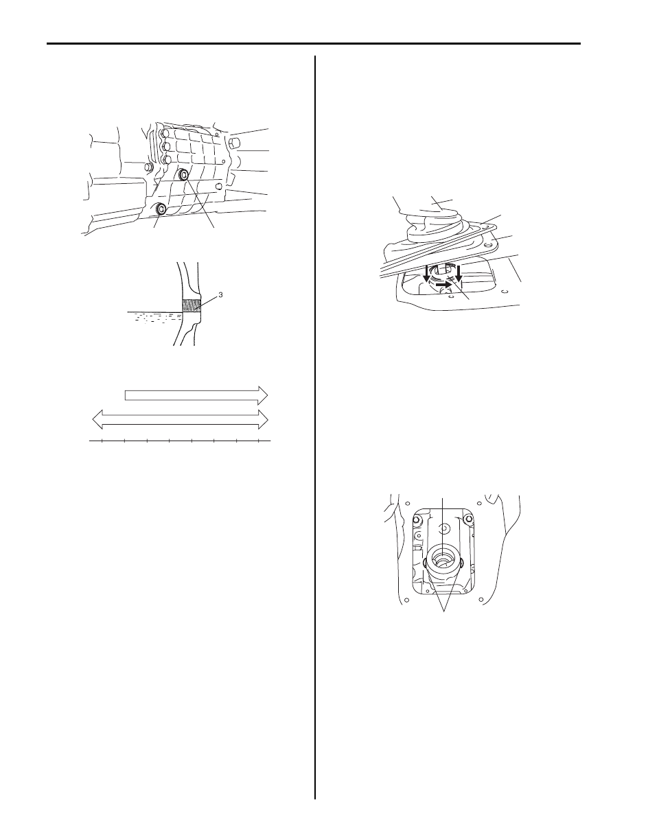
7) Install oil level/filler plug with new washer, and then 

tighten it to specified torque.

Tightening torque
Oil filler plug (b):  35 N·m (3.5 kgf-m, 25.0 lb-ft)

Transmission Shift Control Lever Removal and 
Installation

S6JB0A5226007

Removal

1) Remove front console box referring to “Console Box 

Components in Section 9H”.

2) Lift up boots cover (1), boot (2) and sheet (3).
3) With gear shift control case cover (4) pushed down 

with fingers, turn it to counter clockwise and take out 
shift control lever (5).

Installation

1) Tighten new control lever locating bolts (1) to 

specified torque, if removed.

Tightening torque
Control lever locating bolt (a):  10 N·m (1.0 kgf-
m, 7.5 lb-ft)

2) Apply grease to pivot portions and seat, then install 

shift control lever.

“A”:  Grease 99000–25010 (SUZUKI Super 
Grease A)

1, (a)

2, (b)

I5JB0B520006-01

I5JB0A520022-02

80W-90

Temperature

-30

C

o

F

o

-20

-10

0

10

20

30

40

-22

-4

14

32

50

68

86

104

75W-85, 75W-90

[A]

I5JB0A520021-02

5

2

3

1

4

I5JB0B520111-02

“A”

1, (a) 

I5JB0B520112-01

Manual Transmission/Transaxle: For Diesel Engine Model 5B-48

3) Set shift control lever (2) to gear shift lever case.
4) With gear shift control case cover (1) pushed down 

by hand, turn gear shift control case cover (1) to 
clockwise.

5) Install sheet, boot (1) with boot cover (2) to floor 

panel.

Tightening torque
Control lever boot cover bolt (a):  12 N·m (1.2 
kgf-m, 9.0 lb-ft)

6) Install front console box referring to “Console Box 

Components in Section 9H”.

Transmission Shift Control Lever Inspection

S6JB0A5226008

• Check transmission shift control lever lower portion 

and control lever locating sheet for excessive wear.

• Check boot for damage. 
Correct or replace if necessary.

Back Up Light Switch Removal and Installation

S6JB0A5226009

Removal

WARNING

!


Refrain from work while exhaust No.2 pipe is 
hot.


NOTE

• When replacing switch, use care not to let 

dust enter transmission through switch 
hole.


1) Hoist vehicle and disconnect connector from back up 

light switch.

2) Remove back up light switch (1), washer and pin 

from transmission front case.

Installation
Reverse removal procedure for installation noting the 
following.
• Apply grease to back up light switch pin (3) and then 

install back up light switch (1), new washer (2) and pin 
to transmission front case.

“A”:  Grease 99000–25010 (SUZUKI Super Grease 
A)

Tightening torque
Back up light switch (a):  39 N·m (3.9 kgf-m, 28.5 
lb-ft)

• Check back up light for proper function with ignition 

switch turned ON and reverse position.

1

2

I5JB0B520113-01

2

(a)

1

I5JB0A520027-02

1

I5JB0B520010-01

2

1, (a)

3, “A”

I5JB0B520011-01

5B-49 Manual Transmission/Transaxle: For Diesel Engine Model

Back Up Light Switch Inspection

S6JB0A5226010

Check back up light switch for function using ohmmeter.
If resistance is not as specified below, replace back up 
light switch.

Back up lamp switch specification
Switch ON (Push): Continuity
Switch OFF (Release): No continuity

Gear Shift Lever Case Assembly Removal and 
Installation

S6JB0A5226014

Removal

1) Dismount transmission assembly referring to 

“Manual Transmission Assembly Dismounting and 
Remounting: For Diesel Engine Model”

2) Remove gear shift lever case assembly (1) from 

transmission adapter case.

Installation

NOTE

• Install gear shift lever case to transmission 

adapter case without using sealant for 
functional check.

• Install shift control lever and check to 

make sure that it shifts smoothly 
according to shift pattern as shown in the 
figure.


I5JB0B520012-01

1

I5JB0B520013-01

I5JB0A520010-01

Manual Transmission/Transaxle: For Diesel Engine Model 5B-50

1) Clean mating surface of both adapter case and gear 

shift lever case (2), and uniformly apply sealant to 
lever case as shown in figure by such amount that its 
section is 1.5 mm (0.059 in.) in diameter, and then 
mate it with gear shift lever case.

“A”:  Sealant 99000–31110 (SUZUKI Bond 
No.1215)

2) Install lever case to adapter case, and then tighten 

new lever case bolts (1) to specified torque.

Tightening torque
Gear shift lever front case bolt (a):  23 N·m (2.3 
kgf-m, 17.0 lb-ft)

3) Remount transmission assembly referring to 

“Manual Transmission Assembly Dismounting and 
Remounting: For Diesel Engine Model”

Gear Shift Lever Case Assembly Disassembly 
and Reassembly

S6JB0A5226015

Disassembly

1) Remove gear shift case plate.
2) Drive out gear shift arm pin and gear shift lever pin 

using special tool, and then disassemble 
components parts.

Special tool
(A):  09922–85811

Reassembly

1) Clean all pants thoroughly, inspect them and replace 

with new one as required.

2) Assemble components parts referring to “Gear Shift 

Lever Case Assembly Components: For Diesel 
Engine Model”.

3) Set new gear shift arm inner pin (1) and outer pin (2) 

facing each gap (“a”, “b”) in the opposite direction as 
shown in figure.
Drive gear shift arm pins and gear shift lever pins by 
using special tool.

Special tool
(A):  09922–85811

1, (a)

2

“A”

I5JB0B520014-02

(A)

(A)

I5JB0B520015-01

“a”

“b”

1

2

(A)

I5JB0B520016-01


Content   ..  348  349  350  351   ..