Suzuki Grand Vitara JB416 / JB420 / JB419. Service manual - part 337
 

  Index      Suzuki     Suzuki Grand Vitara JB416 / JB420 / JB419 - service and repair manual 2007 year


Search            copyright infringement  


Content   ..  335  336  337  338   ..


Suzuki Grand Vitara JB416 / JB420 / JB419. Service manual - part 337


5A-139 Automatic Transmission/Transaxle: 

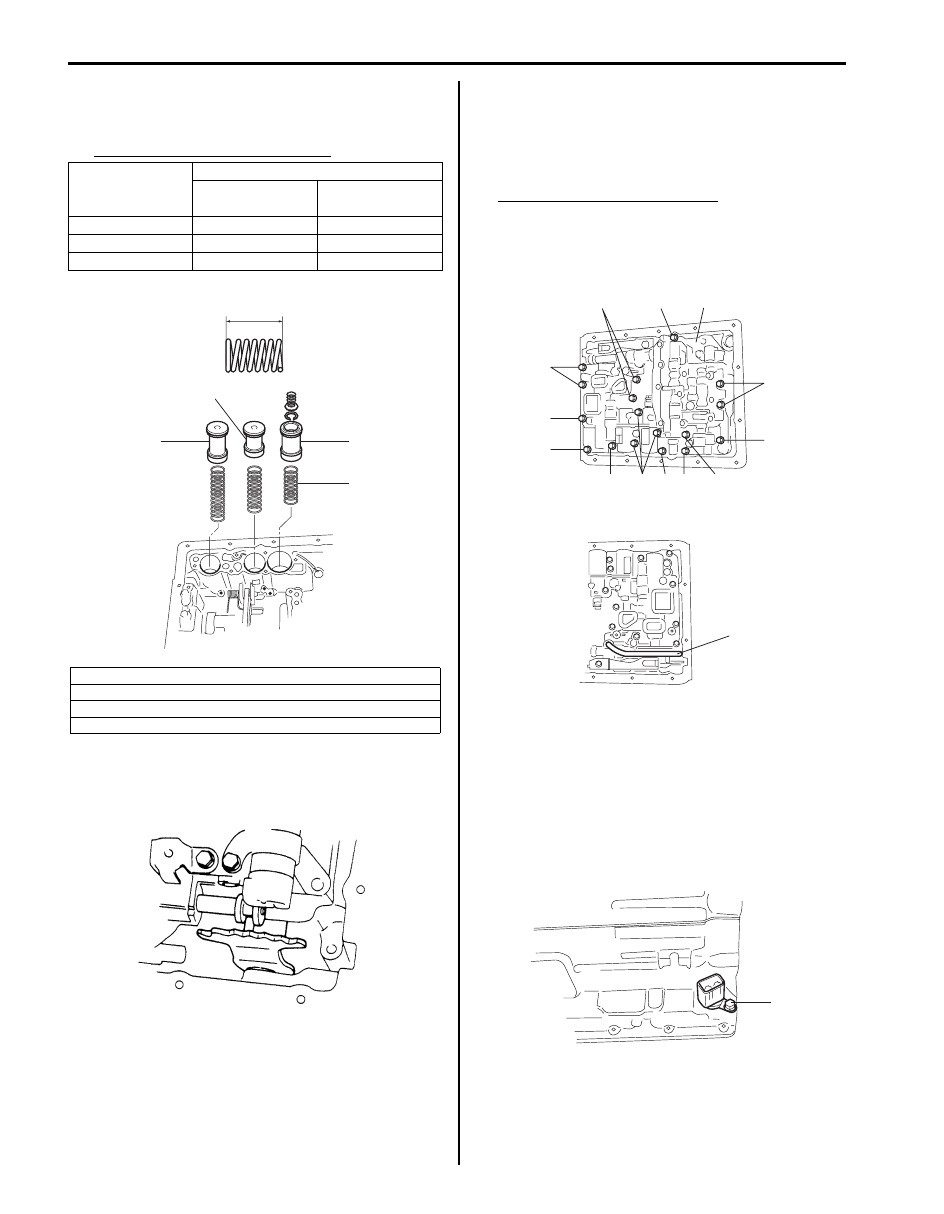
38) Apply A/T fluid to new O-ring and spring and install 

them to accumulator piston and install accumulator 
piston to transmission case.

Accumulator spring specification

39) After confirming that accumulator piston is pushed all 

the way down, match pin of manual shift lever with 
groove in manual valve.

40) Fix valve body (1) by using bolts with each nominal 

length as indicated in the figure and tightening to 
specified torque.

Tightening torque
Valve body bolt:  10 N·m (1.0 kgf-m, 7.5 lb-ft)

Valve body bolt nominal length
“a”: 28 mm (1.10 in.)
“b”: 30 mm (1.18 in.)
“c”: 36 mm (1.42 in.)
“d”: 45 mm (1.77 in.)

41) Install O/D brake applying tube (1).

42) Lubricate new O-ring with A/T fluid and attach it to 

grommet of solenoid wire harness. Then connect 
solenoid wire harness to transmission case and fix it 
with solenoid wire harness clamp. Connect each 
connector to solenoid. And install new gasket and 
brake applying cover.

Tightening torque
Transmission wire connector bolt (a):  16 N·m (
1.6 kgf-m, 11.5 lb-ft)

Accumulator 

piston

Accumulator spring

Spring free 

length “a”

Color

Forward clutch

75.03

White + Blue

Direct clutch

57.74

White + Purple

Second brake

56.16

Purple

1. Forward clutch accumulator piston
2. Direct clutch accumulator piston
3. Second brake accumulator piston
4. Accumulator spring

4

3

1

2

“a”

I5JB0A510140-02

IYSQ01510269-01

“a”

“a”

“a”

1

“b”

“b”

“c”

“c”

“c”

“d”

“d”

“d”

“d”

I5JB0A510141-01

1

I5JB0A510143-02

(a)

I5JB0A510142-01

Automatic Transmission/Transaxle:  5A-140

43) Connect solenoid coupler to each solenoid.
44) Install oil strainer (1) to valve body assembly.

Tightening torque
Oil strainer bolt (a):  5.5 N·m (0.55 kgf-m, 4.0 lb-
ft)

45) Install transmission oil pan (1) with new oil pan 

gasket.

NOTE
Align cutout in oil pan gasket with that in 
transmission case.


Tightening torque
Transmission oil pan bolt:  4.5 N·m (0.45 kgf-m, 
3.5 lb-ft)

46) With wood rough key attached to output shaft, install 

sensor rotor (2) by aligning its key groove with wood 
rough key and install C-ring.

47) Install adapter case (1) with new adapter gasket to 

transmission case and tighten adapter case bolts to 
specified torque.

Tightening torque
Adapter case bolt (a):  31 N·m (3.1 kgf-m, 30.0 lb-
ft)

48) Apply A/T fluid to new O-rings and install them to 

input shaft speed sensor (1) and output shaft speed 
sensor (2), and then install input shaft speed sensor 
(1) and output shaft speed sensor (2).

49) After turning manual shift shaft fully rearward, turn it 

back by 2 notches and set it to “N” range. Then 
install shift switch, lock washer and nut and tighten 
nut. After tightening it, bend claws of lock washer.

Tightening torque
Manual shift shaft nut (a):  12.5 N·m (1.25 kgf-m, 
9.0 lb-ft)

50) With neutral reference line (1) and cut groove (2) in 

switch aligned, tighten lock bolt.

Tightening torque
Transmission range sensor bolt (b):  5.3 N·m (
0.53 kgf-m, 4.0 lb-ft)

1. C-ring

1

(a)

I5JB0A510144-01

IYSQ01510094-01

1

2

I5JB0A510072-01

1

(a)

(a)

I5JB0A510145-01

1

2

I5JB0A510163-01

(b)

1

2

(a)

I5JB0A510147-01

5A-141 Automatic Transmission/Transaxle: 

51) Confirm that torque converter is fully fitted in 

transmission. Confirmation can be done by 
measuring dimension between end surface of 
housing case (2) and drive plate installation seat.

Standard dimension between end surface of 
case housing and drive plate installation seat “a”
17.4 mm (0.69 in.)

52) Check that torque converter turns smoothly and 

apply grease to center piece (1) of torque converter.

Specifications

Bearing and Race Installation Specification

S6JB0A5107002

Bearing and Race Dimension

IYSQ01510279-01

1

2

3

4

8

9

17

18

19

20

5

6

7

10 11

12

13

14

15

16

I5JB0A510013-01

No.

Bearing and race

Inside diameter

Outside diameter

1

Bearing assy, O/D FR

24.32 mm (0.957 in.)

43.20 mm (1.701 in.)

2

Race, thrust O/D FR

24.32 mm (0.957 in.)

39.20 mm (1.543 in.)

3

Bearing, assy, thrust O/D case

24.85 mm (0.978 in.)

37.59 mm (1.480 in.)

4

Race, thrust bearing planetary O/D case

25.03 mm (0.985 in.)

37.35 mm (1.470 in.)

5

Race, thrust planetary No.1

30.00 mm (1.181 in.)

48.54 mm (1.911 in.)

6

Bearing, thrust planetary

28.37 mm (1.117 in.)

46.36 mm (1.825 in.)

7

Race, thrust bearing planetary No.2

27.58 mm (1.086 in.)

44.70 mm (1.760 in.)

8

Race, thrust bearing No.1

24.05 mm (0.947 in.)

37.59 mm (1.480 in.)

9

Bearing, thrust forward clutch

23.41 mm (0.922 in.)

37.47 mm (1.475 in.)

10 Race, thrust bearing No.1

24.05 mm (0.947 in.)

37.59 mm (1.480 in.)

11 Bearing, thrust forward clutch

23.41 mm (0.922 in.)

37.47 mm (1.475 in.)

12 Race, thrust bearing No.2

23.29 mm (0.917 in.)

37.59 mm (1.480 in.)

13 Race, thrust bearing FR sun gear

30.00 mm (1.181 in.)

47.90 mm (1.886 in.)

14 Bearing, thrust FR sun gear

28.37 mm (1.117 in.)

46.36 mm (1.825 in.)

15 Race, thrust bearing FR sun gear

27.58 mm (1.086 in.)

44.70 mm (1.760 in.)

16 Race, thrust bearing

21.41 mm (0.843 in.)

47.50 mm (1.870 in.)

17 Race, thrust bearing RR planetary ring

30.00 mm (1.181 in.)

48.54 mm (1.911 in.)

Automatic Transmission/Transaxle:  5A-142

Tightening Torque Specifications

S6JB0A5107001

NOTE
The specified tightening torque is also described in the following.
“Manual Selector Assembly Components”
“Select Cable Component”
“Oil Cooler Hose and Pipe Components”
“Automatic Transmission Unit Components”
“Oil Pump Components”
“Valve Body Assembly Components”


Reference:
For the tightening torque of fastener not specified in this section, refer to “Fastener Information in Section 0A”.

18 Bearing, thrust RR planetary ring

28.37 mm (1.117 in.)

46.36 mm (1.825 in.)

19 Bearing, thrust output shaft

38.10 mm (1.500 in.)

55.55 mm (2.187 in.)

20 Race, thrust bearing output shaft

39.12 mm (1.540 in.)

57.53 mm (2.264 in.)

No.

Bearing and race

Inside diameter

Outside diameter

Fastening part

Tightening torque

Note

N

m

kgf-m

lb-ft

Fluid pressure check hole bolt

8

0.8 

6.0

)

A/T fluid drain plug

20

2.0 

14.5

)

Manual selector assembly mounting bolt

18

1.8 

13.0

)

Manual select cable nut

13

1.3 

9.5

)

Manual shift shaft nut

12.5

1.25 

9.0

)

 / )

Transmission range sensor bolt

5.3

0.53 

4.0

)

 / )

Manual select lever nut

12.5

1.25 

9.0

)

Input shaft speed sensor bolt

7

0.7 

5.0

)

Output shaft speed sensor bolt

7

0.7 

5.0

)

Oil pump bolt

7.5

0.75 

5.5

)

Center support bolt

26

2.6 

19.0

)

Torque converter housing bolt

35

3.5 

25.5

)

Torque converter housing bolt

58

5.8 

42.0

)

Oil pump bolt

22

2.2 

16.0

)

Parking pawl bracket bolt

7.4

0.74 

5.5

)

Valve body bolt

10

1.0 

7.5

)

Transmission wire connector bolt

16

1.6 

11.5

)

Oil strainer bolt

5.5

0.55 

4.0

)

Transmission oil pan bolt

4.5

0.45 

3.5

)

Adapter case bolt

31

3.1 

30.0

)


Content   ..  335  336  337  338   ..