Suzuki Grand Vitara JB416 / JB420 / JB419. Service manual - part 336
 

  Index      Suzuki     Suzuki Grand Vitara JB416 / JB420 / JB419 - service and repair manual 2007 year


Search            copyright infringement  


Content   ..  334  335  336  337   ..


Suzuki Grand Vitara JB416 / JB420 / JB419. Service manual - part 336


5A-135 Automatic Transmission/Transaxle: 

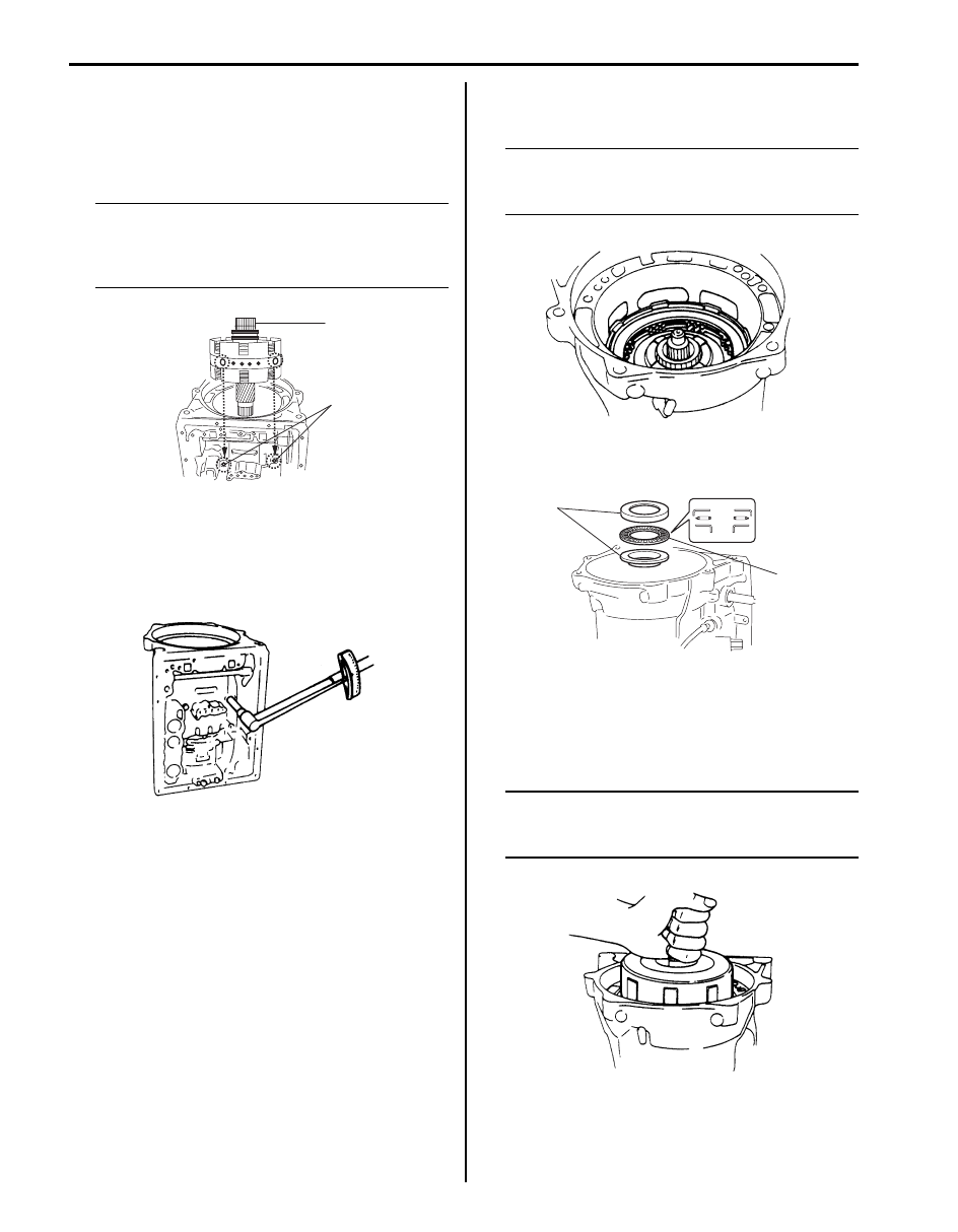
13) After confirming that lugs of all brake plates and 

brake discs are in grooves securely, hold retaining 
ring (1) of planetary sun gear, install center support 
assembly by aligning bolt holes (2) in center support 
and transmission case.

NOTE
Unless retaining ring of planetary sun gear is 
held, brake valve gets off center support and 
that will make it impossible to align fluid 
holes with bolt holes.


14) Tighten center support bolts by certain amount at a 

time till specified tightening torque is obtained.

Tightening torque
Center support bolt:  26 N·m (2.6 kgf-m, 19.0 lb-
ft)

15) Install direct clutch assembly by aligning splines in 

direct clutch cylinder with planetary sun gear.

NOTE
Ends of splines in direct clutch cylinder and 
planetary sun gear should come almost in 
match.


16) Apply grease to thrust bearing (1) and bearing races 

(2), and then install them to direct clutch.

17) Install forward clutch assembly by putting all lugs of 

direct clutch disc hub together and matching them 
with groove cut in direct clutch input hub, and at the 
same time aligning splines in forward clutch hub with 
inner shaft.

NOTE
Use care not to let forward clutch rear No.1 
race and thrust bearing installed to forward 
clutch hub fall off.


1

2

I5JB0A510133-01

IYSQ01510246-01

IYSQ01510247-01

2

1

I5JB0A510134-01

IYSQ01510249-01

Automatic Transmission/Transaxle:  5A-136

18) When clutch disc and plate have been replaced, 

check height difference between forward clutch input 
shaft and transmission case (1) by measuring as 
shown in the figure.

NOTE
If measured value is less than standard 
value, remove forward clutch assembly and 
install it again.


Standard height difference between forward 
clutch input shaft and transmission case
“a”: About 2.0 mm (0.079 in.)

19) Apply grease to thrust bearing (1) and bearing race 

(2), and then install them to forward clutch input 
shaft.

20) Install O/D case by aligning cutout in O/D case (1) 

and that in transmission case.

NOTE
Use care not to drop thrust rear race installed 
to O/D case.


21) Apply grease to thrust washers (1) and install them 

to O/D planetary gear (2) and planetary ring gear (3), 
and then install O/D input shaft assembly to O/D 
case.

NOTE

• Fit claws of thrust washer into holes 

securely.

• Use care not to drop thrust washer 

installed to O/D planetary gear.


22) When clutch disc or plate has been replaced, check 

height difference between O/D case (1) and O/D 
clutch cylinder (2) by measuring it as shown in the 
figure.

NOTE
Measure at the highest point along inner 
circumference of O/D clutch cylinder.


Standard height difference between O/D case 
and O/D clutch cylinder
“a”: About 3.5 mm (0.138 in.)

2. Forward clutch

2. Cutout in automatic transmission

2

1

“a”

I5JB0A510135-01

2

1

I5JB0A510136-01

1

2

I5JB0A510137-02

I5JB0A510138-01

I5JB0A510161-01

5A-137 Automatic Transmission/Transaxle: 

23) Apply A/T fluid to new housing O-ring and install it to 

O/D case. Then install converter housing (1) and 
tighten housing bolt to specified torque.

Tightening torque
Torque converter housing bolt (a):  35 N·m (3.5 
kgf-m, 25.5 lb-ft)
Torque converter housing bolt (b):  58 N·m (5.8 
kgf-m, 42.0 lb-ft)

24) Apply grease to bearing race (1) and thrust bearing 

(2) and install them to O/D clutch cylinder.

25) Apply A/T fluid to new oil pump cover O-ring and 

install it to oil pump assembly. Then install oil pump 
assembly aligning bolt holes in O/D case with those 
in transmission case oil pump assembly. Apply seal 
packing to oil pump assembly bolts and tighten them 
by certain amount of torque at each time one after 
another till specified torque is attained.

Tightening torque
Oil pump bolt (a):  22 N·m (2.2 kgf-m, 16.0 lb-ft)

26) Apply 2 – 4 kg/cm

2

 air pressure into fluid holes in the 

figure as numbered and check operation sound of 
each part.

27) Take down transmission from stand and install new 

gasket and cover plate (1).

28) Measure clearance in shaft direction by applying dial 

gauge (1) to output shaft as shown in the figure.

Standard clearance in shaft direction
0.3 – 0.9 mm (0.012 – 0.035 in.)

I5JB0A510162-01

1

2

I5JB0A510139-01

IYSQ01510257-01

1. O/D clutch

5. Second coast brake

2. O/D brake

6. Second brake

3. Forward clutch

7. Reverse brake

4. Direct clutch

IYSQ01510258-01

1

I5JB0A510089-01

IYSQ01510259-01

Automatic Transmission/Transaxle:  5A-138

29) Check that inner shaft runs smoothly.
30) Apply grease to lip of new oil lip seal and drive in oil 

lip seal with special tool till it contacts transmission 
case.

Special tool
(A):  09923–46020 

31) Install a new spacer (1) to manual shift lever (2).
32) Install manual shift shaft (3) to transmission case 

through manual shift lever.

33) Drive in manual shift lever pin (1) by using hammer.

34) Align hole in sleeve cover with dent in manual shift 

lever and caulk securely with pin punch (1). Then 
check that manual shift shaft turns smoothly.

35) Install parking lock pawl (2), parking pawl pin (1) and 

parking pawl spring (3).

36) Connect parking lock rod (2) to manual shift lever (1) 

as shown in the figure.

37) Install parking lock pawl bracket (1).

Tighten parking pawl bracket bolts (2) to specified 
torque.

Tightening torque
Parking pawl bracket bolt (a):  7.4 N·m (0.74 kgf-
m, 5.5 lb-ft)

IYSQ01510261-01

2

1

3

I4JA01512266-01

1

I4JA01512267-01

1

I4JA01512268-01

2

1

3

I4JA01512269-01

1

2

I4JA01512270-01

1

2, (a)

I4JA01512271-01


Content   ..  334  335  336  337   ..