Suzuki Grand Vitara JB416 / JB420 / JB419. Service manual - part 282
 

  Index      Suzuki     Suzuki Grand Vitara JB416 / JB420 / JB419 - service and repair manual 2007 year


Search            copyright infringement  


Content   ..  280  281  282  283   ..


Suzuki Grand Vitara JB416 / JB420 / JB419. Service manual - part 282


4E-20 ABS: 

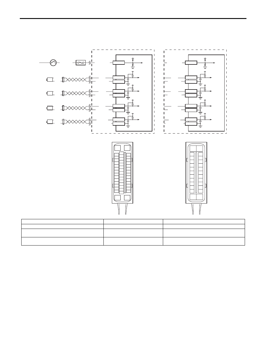
DTC C1021, C1022 / C1025, C1026 / C1031, C1032 / C1035, C1036: Right-Front / Left-Front / Right-
Rear / Left-Rear Wheel Speed Sensor Circuit or Encoder Failure

S6JB0A4504013

Wiring Diagram

1

2

12V

E53-35

GRN/ORN

BLK/YEL

7

[D]

E03

3

4

5

6

BLK

WHT

BLK

WHT

BLU/BLK

GRN/BLK

BLU

GRN

YEL/BLK

YEL

LT GRN

LT GRN/BLK

E53-15

E53-14

E53-2

E53-3

E53-6

E53-5

E53-11

E53-12

12V

12V

12V

12V

BLK

WHT

BLK

WHT

15
16
17
18
19
20
21
22
23
24
25

2
3
4
5
6
7
8
9

10
11
12

1

13

14

26

12V

E03-7

GRN/ORN

8

BLU/BLK

GRN/BLK

BLU

GRN

YEL/BLK

YEL

LT GRN

LT GRN/BLK

E03-21

E03-22

E03-19

E03-18

E03-15

E03-16

E03-25

E03-24

12V

12V

12V

12V

[A]

[B]

[C]

E53

16

1

15

2

3

4

5

6

7

8

9

10

11

12

13

14

17

18

19

20

21

22

23

24

25

26

27

28

29

30

31

32

33

34

35

36

37

38

39

40

41

42

43

44

45

46

47

I6JB01450007-02

[A]: ESP

® model

1. Ignition switch

5. Left-rear wheel speed sensor

[B]: Non-ESP

® model

2. Junction block assembly

6. Right-rear wheel speed sensor

[C]: ESP

® control module connector (viewed from 

terminal side)

3. Left-front wheel speed sensor

7. ESP

® hydraulic unit / control module assembly

[D]: ABS control module connector (viewed from 

terminal side)

4. Right-front wheel speed sensor

8. ABS hydraulic unit / control module assembly

ABS: 4E-21

DTC Detecting Condition
The ABS (ESP

®) control module monitors the voltage at the terminal of each sensor while the ignition switch is ON. 

When the voltage is not within the specified range, an applicable DTC will be set. Also, when no sensor signal is 
inputted at running, an applicable DTC will be set.

NOTE
When the vehicle was operated in any of the following ways, one of these DTCs may be set even when 
the sensor is in good condition. If such possibility is suspected, clear DTC once referring to “DTC 
Clearance” 
and then performing the driving test as described in Step 2 of “ABS Check”, check whether 
or not any abnormality exists.
• The vehicle was driven with parking brake pulled.
• Wheel spin occurred while driving.
• Wheel(s) was turned while the vehicle was jacked up.
• The vehicle was stuck.


DTC Troubleshooting

Step

Action

Yes

No

1

Was “ABS Check” performed?

Go to Step 2.

Go to “ABS Check”.

2

1) Turn ignition switch OFF.
2) Disconnect ABS (ESP

®) control module connector.

3) Check for proper connection to ABS (ESP

®) control 

module at each sensor terminal.

4) If OK, then turn ignition switch ON and measure voltage 

between applicable sensor terminal of module connector 
and vehicle body ground.

Is it 0 V?

Go to Step 3.

ABS wheel speed 
sensor circuit shorted to 
power.

3

1) Disconnect applicable wheel speed sensor coupler with 

ignition switch OFF.

2) Measure resistance between the following points.

• Both ABS (ESP

®) control module connector (1) 

terminals a pair of applicable sensor terminals. This 
check result should be no continuity.

• Between applicable sensor terminal of ABS (ESP

®) 

control module connector and vehicle body ground. 
This check result should be no continuity.

• Between applicable sensor terminal of module 

connector and corresponding terminal of wheel speed 
sensor connector (2) in main harness (for front 
sensor) or floor harness (for rear sensor). This check 
result should be continuity.

Are each check results OK?

Go to Step 4.

Circuit open or short to 
ground.

4

1) Remove applicable wheel speed sensor.
2) Check sensor for damage or foreign material attached.

Is it in good condition?

Go to Step 5.

Clean, repair or replace.

1

2

I5JB0A450014-02

4E-22 ABS: 

5

Check front and/or rear encoder for the following (remove 
front and/or rear drive shaft):
• Encoder surface neither crack nor damaged
• No foreign material being attached
• Encoder not being eccentric
• Wheel bearing free from excessive play

Are they in good condition?

Go to Step 6.

Clean, repair or replace 
wheel hub assembly.

6

1) Install wheel speed sensor to knuckle.
2) Tighten sensor bolt to specified torque and check that 

there is no clearance between sensor and knuckle.

Is it OK?

Go to Step 7.

Replace ABS wheel 
speed sensor.

7

Refer to “Front and Rear Wheel Speed Sensor On-Vehicle 
Inspection”,
check output voltage or waveform.

Is specified voltage and/or waveform obtained?

Substitute a known-
good ABS (ESP

®) 

hydraulic unit / control 
module assembly and 
recheck.

Replace sensor and 
recheck.

Step

Action

Yes

No

ABS: 4E-23

DTC C1041 / C1042 / C1043 / C1044 / C1045 / C1046 / C1051 / C1052 / C1053 / C1054 / C1055 / C1056: 
Inlet Solenoid Circuit Failure, Outlet Solenoid Circuit Failure, Master Cylinder Cut Solenoid Circuit 
Failure, Low Pressure Solenoid Circuit Failure

S6JB0A4504014

DTC C1041 / C1045 / C1051 / C1055: Right-Front / Left-Front / Right-Rear / Left-Rear Inlet Solenoid 
Circuit Failure
DTC C1042 / C1046 / C1052 / C1056: Right-Front / Left-Front / Right-Rear / Left-Rear Outlet Solenoid 
Circuit Failure
DTC C1043 / C1044: Master Cylinder Cut Solenoid Circuit No. 1 / No. 2 Failure
DTC C1053 / C1054: Low Pressure Solenoid Circuit No. 1 / No. 2 Failure

NOTE
The DTC C1043, C1044, C1053 and C1054 are DTC only for ESP

®


Wiring Diagram

WHT/RED

1

2

6

5

BLK

BLK

5V

12V

E03-14

E03-13

E03-26

7

WHT/RED

1

2

6

5

BLK

BLK

5V

12V

E53-1

E53-16

E53-47

7

[D]

[C]

E03

15
16
17
18
19
20
21
22
23
24
25

2
3
4
5
6
7
8
9

10
11
12

1

13

14

26

[B]

[A]

E53

16

1

15

2

3

4

5

6

7

8

9

10

11

12

13

14

17

18

19

20

21

22

23

24

25

26

27

28

29

30

31

32

33

34

35

36

37

38

39

40

41

42

43

44

45

46

47

3

4

I6JB01450008-01

[A]: ESP

® model

1. Battery

5. Solenoid valve


Content   ..  280  281  282  283   ..