Suzuki Grand Vitara JB416 / JB420 / JB419. Service manual - part 281
 

  Index      Suzuki     Suzuki Grand Vitara JB416 / JB420 / JB419 - service and repair manual 2007 year


Search            copyright infringement  


Content   ..  279  280  281  282   ..


Suzuki Grand Vitara JB416 / JB420 / JB419. Service manual - part 281


4E-16 ABS: 

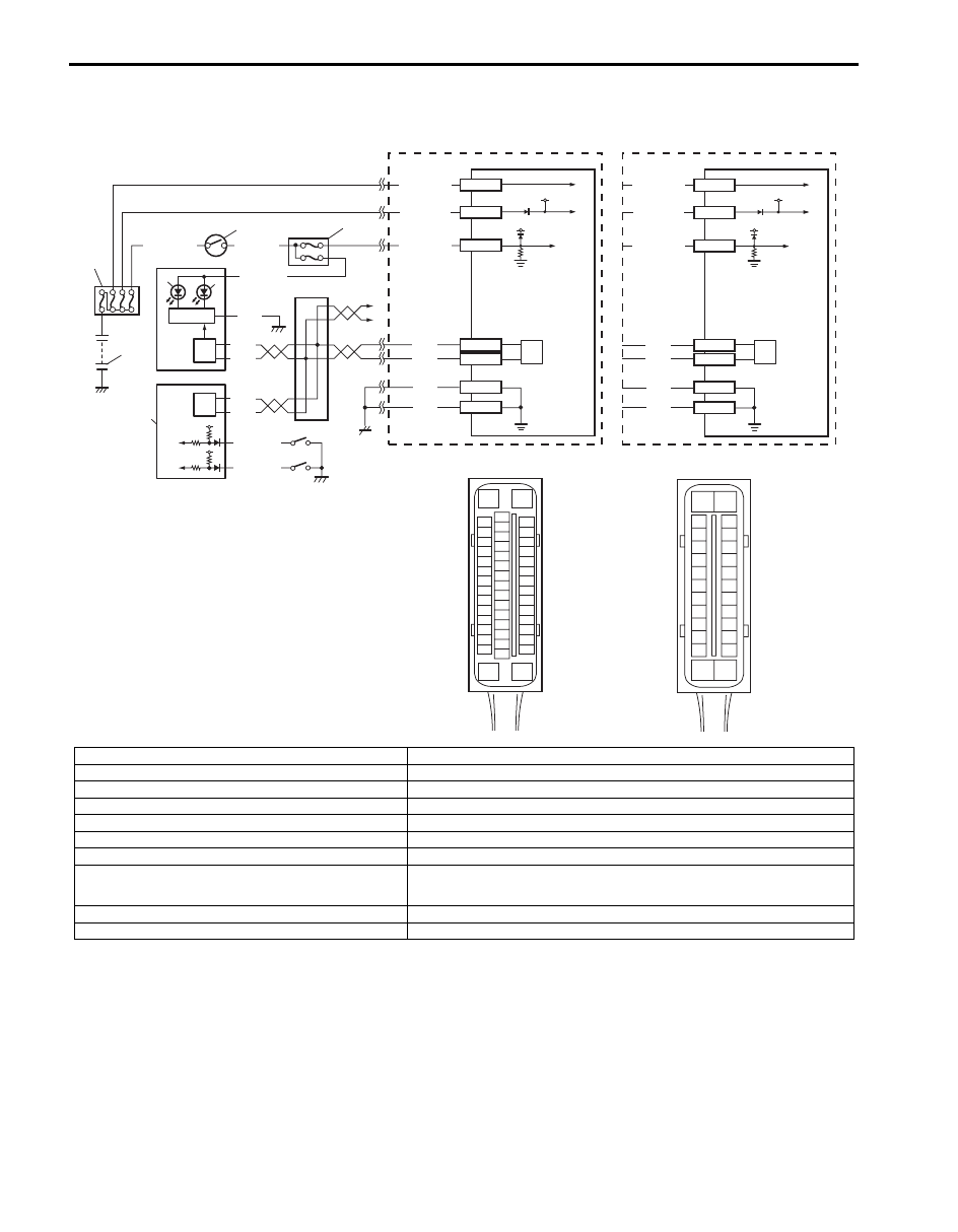
EBD Warning Light (Brake Warning Light) Comes ON Steady

S6JB0A4504010

Wiring Diagram

Circuit Description
EBD warning light (brake warning light) is controlled by parking brake switch, brake fluid level switch and ABS (ESP

®) 

control module assembly through light driver module in combination meter.
EBD warning light turns ON when parking brake switch is ON and/or brake fluid level is lower than minimum level.
The information of parking brake switch and brake fluid level are transmitted from BCM to light driver module in 
combination meter through CAN communication line.

3

4

2

1

[C]

E53-16

E53-47

12V

12V

E53-32

E53-1

E53-35

GRN/ORN

PPL/RED

BLK/YEL

WHT/GRN

WHT/RED

WHT/BLU

BLK

BLK

BLK

RED

WHT

RED

WHT

E53-13
E53-44

15

16

10

5

7

8

6

9

E53

16

1

15

2

3

4

5

6

7

8

9

10

11

12

13

14

17

18

19

20

21

22

23

24

25

26

27

28

29

30

31

32

33

34

35

36

37

38

39

40

41

42

43

44

45

46

47

E03-13

E03-26

12V

12V

E03-1

E03-14

E03-7

GRN/ORN

WHT/RED

WHT/BLU

BLK

BLK

RED

WHT

E03-12
E03-6

13

9

[D]

E03

15
16
17
18
19
20
21
22
23
24
25

2
3
4
5
6
7
8
9

10
11
12

1

13

14

26

9

RED

WHT

9

12

11

[A]

[B]

RED/BLK

12V

12V

RED/BLK

14

I6JB01450006-02

[A]: ESP

® model

7. EBD warning light (Brake warning light)

[B]: Non-ESP

® model

8. Light driver module

[C]: ESP

® control module connector (viewed from terminal side)

9. CAN driver

[D]: ABS control module connector (viewed from terminal side)

10. BCM

1. Battery

11. Parking brake switch

2. Main fuse box

12. Brake fluid level switch

3. Ignition switch

13. Junction connector

4. Junction block assembly

14. To TCM (if equipped), 4WD control module (if equipped), keyless start control module 

(if equipped), immobilizer control module (ICM) (if equipped) and steering angle 
sensor (if equipped)

5. Combination meter

15. ESP

® hydraulic unit / control module assembly

6. ABS warning light

16. ABS hydraulic unit / control module assembly

ABS: 4E-17

Troubleshooting

Serial Data Link Circuit Check

S6JB0A4504011

Step

Action

Yes

No

1

1) Make sure that:

• Parking brake is completely released.
• Brake fluid level is upper than the minimum level.

Are the check results OK?

Go to Step 2.

Release parking brake 
completely and/or 
replenish brake fluid.

2

1) Turn ignition switch to ON position.

Does “ABS” warning light come on steady?

Perform “ABS Warning 
Light Comes ON 
Steady” p
reviously 
outlined.

Go to Step 3.

3

1) CAN communication circuit between combination meter, 

ABS (ESP

®) control module and BCM referring to “DTC 

U1073: Control Module Communication Bus Off (Petrol 
Engine Model)”
.

Is CAN communication circuit in good condition?

Substitute a known-
good combination meter 
and recheck. If ABS 
warning light remains 
ON, substitute a known-
good ABS (ESP

®) 

hydraulic unit / control 
module assembly and 
recheck.

Repair or replace.

3

4

2

1

12V

12V

E03-1

E03-14

E03-7

GRN/ORN

PPL/RED

BLK/YEL

WHT/GRN

WHT/RED

WHT/BLU

E03-13

E03-26

BLK

BLK

BLK

RED

WHT

RED

WHT

E03-12
E03-6

PPL/WHT

12V

+BB

E03-5

[A]

E03

10

11

9

8

G

G1

5

7

6

12

15
16
17
18
19
20
21
22
23
24
25

2
3
4
5
6
7
8
9

10
11
12

1

13

14

26

I5JB0A450012-02

[A]: ABS hydraulic unit / control module connector (viewed from terminal side)

7. Light driver module

1. Battery

8. Data link connector (DLC)

2. Main fuse box

9. To ECM, TCM (if equipped), BCM, SDM and 4WD control module

3. Ignition switch

10. Junction connector 

4. Junction block assembly

11. To TCM (if equipped), BCM, 4WD control module (if equipped), 

immobilizer control module (ICM) (if equipped) and keyless start control 
module (if equipped)

5. Combination meter

12. ABS hydraulic unit / control module assembly

6. ABS warning light 

4E-18 ABS: 

Inspection

Step

Action

Yes

No

1

1) Turn ignition switch to ON position.

Does ABS warning light come ON?

Go to Step 2.

Go to Step 6.

2

1) Turn ignition switch to OFF position.

Are main fuses for ABS pump motor and ABS solenoid in 
good condition?

Go to Step 3.

Replace fuse and check 
for short.

3

1) Disconnect ABS hydraulic unit / control module 

connector.

2) Check for proper connection to ABS hydraulic unit / 

control module connector at terminal “E03-7”.

3) If OK then turn ignition switch to ON position and 

measure voltage between terminal “E03-7” and vehicle 
body ground.

Is it 10 – 14 V?

Go to Step 4.

“GRN/ORN” wire circuit 
open.

4

1) Turn ignition switch to OFF position.
2) Check for proper connection to ABS hydraulic unit / 

control module connector at terminals “E03-1” and “E03-
14”.

3) If OK then turn ignition switch to ON position and 

measure voltage between each terminal of “E03-1”, 
“E03-14” and vehicle body ground.

Are they 10 – 14 V?

Go to Step 5.

“WHT/RED” and/or 
“WHT/BLU” wire circuit 
open.

5

1) Turn ignition switch to OFF position.
2) Check for proper connection to ABS hydraulic unit / 

control module connector at terminals “E03-13” and 
“E03-26”.

3) If OK, measure resistance between each terminal of 

“E03-13”, “E03-26” and vehicle body ground.

Are resistance less than 2 

?

Go to Step 6.

Ground circuit for ABS 
hydraulic unit / control 
module open or high 
resistance.

6

1) Check if communication is possible by trying 

communication with other controller (ECM, TCM, BCM, 
4WD control module or SDM).

Is it possible to communicate with other controller?

Go to Step 7.

Repair open in common 
section of serial data 
circuit (“PPL/WHT” wire 
circuit) used by all 
controllers or short to 
ground or power circuit 
which has occurred 
somewhere in serial 
data circuit (“PPL/WHT” 
wire circuit).

7

1) Turn ignition switch to ON position.
2) Measure voltage between terminal B of data link 

connector and vehicle body ground.

Is voltage 10 – 12 V?

Go to step 8.

Terminal B circuit open 
or shorted to ground.

8

1) Turn ignition switch to OFF position.
2) Measure resistance between the following terminals;

• Terminal G of data link connector and vehicle body 

ground.

• Terminal G1 of data link connector and vehicle body 

ground.

Is each resistance 1 

 or less?

Go to step 9.

Terminal G and/or G1 
circuit open or high 
resistance.

ABS: 4E-19

DTC C1015: G Sensor Circuit Failure (4WD Model)

S6JB0A4504012

For vehicle equipped with ESP

®, go to “DTC C1015 / C1017 / C1023: Longitudinal G Sensor / Lateral G Sensor / Yaw 

Rate Sensor in Yaw Rate / G Sensor Assembly Failure in Section 4F”.

Description
If the signal voltage of G sensor while at a stop does not vary from that while running, this DTC is set. (for 4WD 
vehicle)
Therefore, this DTC may be set when a vehicle is lifted up and its wheel(s) is turned. In such case, clear the DTC and 
check again.

DTC Troubleshooting

1) Ignition switch OFF.
2) Check for proper connection from harness to control module.
3) If OK, substitute an ABS hydraulic unit/control module assembly with correct part number.
4) Recheck system.

9

1) Turn ignition switch to OFF position.
2) Check proper connection at “E03-5” (“PPL/WHT” wire) 

terminal for serial data circuit.

3) If OK, then check resistance between “E03-5” (“PPL/

WHT” wire) terminal and “PPL/WHT” wire terminal (2) for 
serial data circuit in DLC (1).

Is resistance 1 

 or less?

Substitute a known-
good ABS hydraulic unit 
/ control module and 
recheck.

Repair high resistance 
or open in “PPL/WHT” 
wire circuit for anti lock 
brake system.

Step

Action

Yes

No

I4RS0A450013-02


Content   ..  279  280  281  282   ..