Suzuki Grand Vitara JB419. Service manual - part 121
 

  Index      Suzuki     Suzuki Grand Vitara JB419 (with F9Q engine) - service and repair manual 2007 year


Search            


Content   ..  119  120  121  122   ..


Suzuki Grand Vitara JB419. Service manual - part 121


Power Assisted Steering System:  6C-10

P/S Pump Removal and Installation

S5JB0B6306019

Removal

CAUTION

!


Never disassemble P/S pump for diesel 
engine model. Disassembly will spoil its 
original performance. If faulty condition is 
found, replace it with new one.


NOTE
Be sure to clean each joint of suction and 
discharge sides thoroughly before removal.


1) Disconnect negative (–) cable at battery.
2) Remove generator referring to “Generator 

Dismounting and Remounting in Section 1J”.

3) Take out P/S fluid in reservoir with syringe or such.
4) Disconnect high pressure pipe and suction hose 

from P/S pump.

NOTE
As fluid flows out of disconnected joints, put 
a receptacle under joints or a plug to pipe.


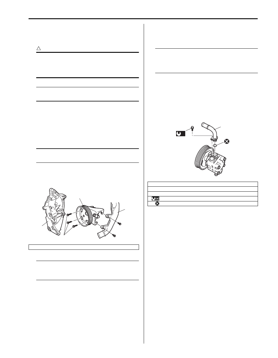
5) Remove P/S pump mounting bolts (1).
6) Remove radiator inlet pipe No.1 bracket (3), and 

then remove P/S pump (2).

NOTE
Plug each port of removed pump to prevent 
dust or any other foreign matter from 
entering.


Installation
Reverse removal procedure, and then noting the 
following instructions.

NOTE
Fill specified power steering fluid after 
installation and bleed air without failure. 
(Refer to “P/S System Air Bleeding 
Procedure in related manual”.)


Tightening torque
P/S pump mounting bolt:  25 N·m (2.5 kgf-m, 18.0 lb-
ft)
P/S pump high pressure pipe union bolt:  60 N·m (
6.0 kgf-m, 43.0 lb-ft)

P/S Pump Assembly Components

S5JB0B6306022

P/S Pump Inspection

S5JB0B6306025

Check P/S pump as follows.
• Damage of pump body.
• Oil leakage from pump body.
• Wear and damage of pulley.
• Abnormal noise when pulley is turned by hand.
If abnormality is found, replace P/S pump with new one.

4. P/S pump bracket

4

3

2

1

I5JB0B630007-01

1. Suction connector
2. O-ring
3. Suction connector bolt

: 3.7 N

⋅m (0.37 kgf-m, 2.7 lb-ft)

: Do not reuse.

3

1

2

(a)

I5JB0B630008-01

6C-11 Power Assisted Steering System: 

Specifications

Tightening Torque Specifications

S5JB0B6307001

NOTE
The specified tightening torque is also described in the following.
“P/S Hose / Pipe Components”
“P/S Pump Assembly Components”


Reference:
For the tightening torque of fastener not specified in this section, refer to “Fastener Information in Section 0A”.

Special Tools and Equipment

Special Tool

S5JB0B6308002

Fastening part

Tightening torque

Note

N

m

kgf-m

lb-ft

Steering lower shaft bolt

25

2.5 

18.5

)

Gear case high pressure pipe union bolt

35

3.5 

25.5

)

Gear case cylinder pipe flare nut

25

2.5 

18.0

)

Gear case mounting bolt

105

10.5 

76.0

)

Gear case low pressure pipe flare nut

35

3.5 

25.5

)

P/S pump bracket bolt

55

5.5 

40.0

)

Stabilizer bar mount bracket mount bolt

60

6.0 

43.0

)

P/S pump mounting bolt

25

2.5 

18.0

)

P/S pump high pressure pipe union bolt

60

6.0 

43.0

)

09915–77412

09915–77420

Oil pressure gauge

Oil pressure gauge 
attachment and hose set

)

)

Table of Contents 7- i

7

Section 7

CONTENTS

HVAC

Precautions ................................................. 7-*

Precautions.............................................................. 7-*

Precautions for HVAC............................................ 7-*

Heater and Ventilation............................. 7A-1

General Description .............................................7A-1

Heater and Ventilation Construction ....................7A-*

Additional Heater System Description................. 7A-1

Body Ventilation Construction..............................7A-*
On-Board Diagnostic System Description (for 

Vehicle without A/C)...........................................7A-*

HVAC Control System Description (for 

Vehicle without A/C)...........................................7A-*

Schematic and Routing Diagram........................7A-1

Heater and Ventilation Wiring Circuit Diagram .....7A-*

Electronic Control Input / Output Diagram (for 

Vehicle without A/C).......................................... 7A-1

Additional Heater System Input / Output 

Diagram ............................................................ 7A-2

Component Location ...........................................7A-2

Electronic Components Location for Heater 

(for Vehicle without A/C) ....................................7A-*

Additional Heater System Component 

Location ............................................................ 7A-2

Diagnostic Information and Procedures............7A-3

Heater and Ventilation System Check .................7A-*
Visual Inspection..................................................7A-*
DTC Check ..........................................................7A-*
DTC Clearance ....................................................7A-*
DTC Table............................................................7A-*
Fail-Safe Table.....................................................7A-*
Scan Tool Data ....................................................7A-*

Heater and Ventilation Symptom Diagnosis........ 7A-3

Repair Instructions ..............................................7A-4

Blower Unit and Heater Unit Components ...........7A-*
HVAC Unit Removal and Installation (for 

Vehicle without A/C)...........................................7A-*

HVAC Air Filter Removal and Installation (for 

Vehicle without A/C)...........................................7A-*

HVAC Air Filter Inspection (for Vehicle without 

A/C)....................................................................7A-*

Blower Motor Removal and Installation................7A-*
Blower Motor Inspection ......................................7A-*

Blower Motor Controller Removal and 

Installation ......................................................... 7A-*

Blower Motor Controller Inspection ..................... 7A-*
Blower Motor Relay Inspection ........................... 7A-*

Heater Core Removal and Installation ................7A-4

HVAC Control Module Removal and 

Installation ......................................................... 7A-*

HVAC Control Module and Its Circuits 

Inspection (for Vehicle without A/C) .................. 7A-*

Air Flow Control Actuator Removal and 

Installation ......................................................... 7A-*

Air Flow Control Actuator Inspection................... 7A-*
Temperature Control Actuator Removal and 

Installation ......................................................... 7A-*

Temperature Control Actuator Inspection ........... 7A-*
Air Intake Control Actuator Removal and 

Installation ......................................................... 7A-*

Air Intake Control Actuator Inspection................. 7A-*
Actuator Linkage Inspection................................ 7A-*
Center Ventilation Louver Removal and 

Installation ......................................................... 7A-*

Side Ventilation Louver Removal and 

Installation ......................................................... 7A-*

Rear Duct Components....................................... 7A-*
Rear Duct Removal and Installation.................... 7A-*

Additional Heater Relay Inspection .....................7A-4
Additional Heater Assembly On-Vehicle 

Inspection..........................................................7A-5

Additional Heater Assembly Removal and 

Installation .........................................................7A-5

Specifications.......................................................7A-6

Tightening Torque Specifications........................7A-6

Air Conditioning System......................... 7B-1

Precautions...........................................................7B-1

A/C System Caution............................................ 7B-*
Precautions on Servicing A/C System ................ 7B-*
Precautions in Diagnosing Trouble ..................... 7B-*
Precautions on Handling Refrigerant HFC-

134a (R-134a) ................................................... 7B-*

Precautions on Servicing Refrigerant Line..........7B-1

Precautions on Refrigerant Recovery ................. 7B-*
Precautions on Refrigerant Charge..................... 7B-*

Precautions on Replenishing Compressor Oil ....7B-2

NOTE
For the items with asterisk (*) in the “CONTENTS” below, refer to the same section of the service manual 
mentioned in the “FOREWORD” of this manual.

7-ii Table of Contents

Precautions on Servicing Compressor 

Assembly .......................................................... 7B-*

General Description .............................................7B-3

AUTO A/C System Description ........................... 7B-*
HVAC Control System Description...................... 7B-*
HVAC Control Module Operation Description ..... 7B-*

A/C Refrigerant Type Description .......................7B-3

Sub-Cool A/C System Description ...................... 7B-*
A/C Evaporator Temperature Sensor 

Description ........................................................ 7B-*

On-Board Diagnostic System Description........... 7B-*

Schematic and Routing Diagram........................7B-3

Air Flow Diagram of A/C System......................... 7B-*

Auto A/C Electronic Control Input / Output 

Diagram ............................................................7B-3

A/C System Wiring Circuit Diagram ....................7B-4

Component Location ...........................................7B-6

A/C Control System Components Location.........7B-6

Diagnostic Information and Procedures............7B-7

Air Conditioning System Check........................... 7B-*
DTC Check.......................................................... 7B-*
DTC Clearance ................................................... 7B-*
DTC Table........................................................... 7B-*
Fail-Safe Table.................................................... 7B-*

Scan Tool Data ...................................................7B-7

Visual Inspection ................................................. 7B-*

A/C System Performance Inspection ..................7B-9
A/C System Symptom Diagnosis ......................7B-14

Abnormal Noise Diagnosis.................................. 7B-*
Abnormal Noise Symptom Diagnosis of A/C 

System .............................................................. 7B-*

DTC B1502: Inside Air Temperature Sensor 

and/or Its Circuit Malfunction ............................ 7B-*

DTC B1503: A/C Evaporator Air Temperature 

Sensor and/or Its Circuit Malfunction ................ 7B-*

DTC B1504: Sunload Sensor and/or Its 

Circuit Malfunction ............................................ 7B-*

DTC B1511: Temperature Control Actuator 

(Position Sensor) and/or Its Circuit 
Malfunction........................................................ 7B-*

DTC B1512: Air Flow Control Actuator 

(Position Sensor) and/or Its Circuit 
Malfunction........................................................ 7B-*

DTC B1513: Temperature Control Actuator 

and/or Its Circuit Malfunction ............................ 7B-*

DTC B1514: Air Flow Control Actuator and/or 

Its Circuit Malfunction........................................ 7B-*

DTC B1520: Temperature Selector and/or Its 

Circuit Malfunction ............................................ 7B-*

DTC B1521: Blower Speed Selector and/or Its 

Circuit Malfunction ............................................ 7B-*

DTC B1530: Air Intake Control Actuator 

(Position Sensor) and/or Its Circuit 
Malfunction........................................................ 7B-*

DTC B1531: Air Intake Control Actuator and/

or Its Circuit Malfunction ................................... 7B-*

DTC B1546: A/C Refrigerant Pressure 

Malfunction........................................................ 7B-*

DTC B1551: Serial Communication Circuit 

Malfunction........................................................ 7B-*

DTC B1552: Serial Communication Circuit 

Malfunction........................................................ 7B-*

DTC B1553: CAN Communication Circuit 

Malfunction........................................................ 7B-*

DTC B1556: Camshaft Position (CMP) 

Sensor and/or Its Circuit Malfunction ................ 7B-*

DTC B1557: Wheel Speed Sensor and/or Its 

Circuit Malfunction...........................................7B-16

DTC B1561: Engine Coolant Temperature 

Sensor and/or Its Circuit Malfunction ..............7B-17

DTC B1562: Outside Air Temperature Sensor 

and/or Its Circuit Malfunction............................. 7B-*

DTC B1563: A/C Refrigerant Pressure 

Sensor and/or Its Circuit Malfunction ..............7B-17

HVAC Control Module and Its Circuits 

Inspection.......................................................... 7B-*

Repair Instructions ............................................7B-18

Operation Procedure for Charging A/C with 

Refrigerant ......................................................7B-18

A/C Condenser Assembly On-Vehicle 

Inspection.......................................................... 7B-*

A/C Condenser Assembly Removal and 

Installation ......................................................... 7B-*

Desiccant Removal and Installation .................... 7B-*
HVAC Air Filter Removal and Installation ........... 7B-*
HVAC Air Filter Inspection .................................. 7B-*
HVAC Unit Components ..................................... 7B-*

HVAC Unit Removal and Installation ................7B-22

A/C Evaporator Removal and Installation ........... 7B-*
A/C Evaporator Inspection .................................. 7B-*
A/C Evaporator Temperature Sensor 

Removal and Installation................................... 7B-*

A/C Evaporator Temperature Sensor 

Inspection.......................................................... 7B-*

Expansion Valve On-Vehicle Inspection ............. 7B-*
Expansion Valve Removal and Installation ......... 7B-*

A/C Refrigerant Pressure Sensor and Its 

Circuit Inspection.............................................7B-23

A/C Refrigerant Pressure Sensor Removal 

and Installation ................................................7B-24

Sunload Sensor Removal and Installation .......... 7B-*
Sunload Sensor Inspection ................................. 7B-*
Inside Air Temperature Sensor Removal and 

Installation ......................................................... 7B-*

Inside Air Temperature Sensor Inspection.......... 7B-*
Outside Air Temperature Sensor Removal 

and Installation .................................................. 7B-*

Outside Air Temperature Sensor Inspection ....... 7B-*
Air Flow Control Actuator Removal and 

Installation ......................................................... 7B-*

Air Flow Control Actuator Inspection................... 7B-*
Air Intake Control Actuator Removal and 

Installation ......................................................... 7B-*

Air Intake Control Actuator Inspection................. 7B-*
Temperature Control Actuator Removal and 

Installation ......................................................... 7B-*

Temperature Control Actuator Inspection ........... 7B-*


Content   ..  119  120  121  122   ..