Suzuki Grand Vitara JB419. Service manual - part 120
 

  Index      Suzuki     Suzuki Grand Vitara JB419 (with F9Q engine) - service and repair manual 2007 year


Search            


Content   ..  118  119  120  121   ..


Suzuki Grand Vitara JB419. Service manual - part 120


Power Assisted Steering System:  6C-6

Repair Instructions

P/S Fluid Level Check

S5JB0B6306002

With engine stopped, check fluid level indicated on P/S 
fluid reservoir, which should be between “UPPER” and 
“LOWER” marks. If it is lower than “LOWER” mark, fill 
fluid up to “UPPER” mark.

NOTE

• Be sure to use an specified power steering 

fluid.

• Fluid level should be checked when fluid is 

cool.


P/S Fluid Leakage Check

S5JB0B6306003

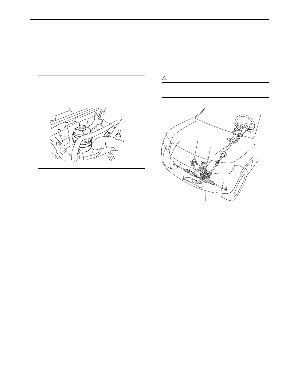
Start engine and turn steering wheel fully to the right and 
left so that maximum hydraulic pressure is provided. 
Then visually check P/S gear case assembly (1), P/S 
pump (2) and P/S fluid reservoir (3) themselves and 
each joint of their connecting pipes for leakage.

CAUTION

!


Never keep steering wheel turned fully for 
longer than 10 seconds.


P/S Pump and A/C Compressor (If Equipped) 
Drive Belt Inspection

S5JB0B6306006

Refer to “Accessory Drive Belt Inspection in Section 1J”.

I5JB0B630004-01

3

2

1

I5JB0B630001-01

6C-7 Power Assisted Steering System: 

P/S Gear Case Assembly Removal and 
Installation

S5JB0B6306014

CAUTION

!


Never disassemble P/S gear case assembly. 
Disassembling will adversely affect original 
performance of P/S gear case assembly.


Removal

1) Disconnect negative (–) cable at battery.
2) Take out P/S fluid in reservoir with syringe or such.
3) Hoist vehicle and remove both right and left wheels.
4) Disconnect both right and left tie-rod ends from 

knuckle referring to Step 2) to 3) of “Removal” in 
“Tie-Rod End Removal and Installation in related 
manual”.

5) Remove generator referring to “Generator 

Dismounting and Remounting in Section 1J”.

6) Remove P/S pump referring to “P/S Pump Removal 

and Installation”.

7) Remove P/S pump bracket (1).

8) Disconnect steering lower shaft assembly (1) from 

pinion shaft of P/S gear case assembly (2) referring 
to Step 5) of “Removal” in “Steering Lower Shaft 
Assembly Removal and Installation in Section 6B in 
related manual”.

9) Disconnect high pressure pipe (3) from P/S gear 

case assembly.

10) Disconnect low pressure pipe (4) from P/S gear case 

assembly.

11) Remove P/S gear case cylinder pipes (5) from P/S 

gear case assembly.

12) Remove stabilizer bar mount bolt and stabilizer joint.

NOTE
Do not remove stabilizer bar from vehicle.


13) Remove stabilizer bar mount bracket (2) from left 

side of front suspension frame.

1

I5JB0B630005-01

1

2

3

5

4

I5JB0A630017-01

1

2

I5JB0A630018-01

Power Assisted Steering System:  6C-8

14) Remove bolts (1) and then take off P/S gear case 

assembly from left side of vehicle.

NOTE
P/S gear case assembly cannot be removed 
from the right side of vehicle.


Installation
Reverse removal procedure for installation of P/S gear 
case, noting the following points.
• After confirming that front tire is in straight position, 

install P/S gear case to body temporarily. Next, with 
tie-rod end installed to knuckle, set rack in position 
close to neutral. Then obtain the neutral state by 
aligning match marks (1) on pinion shaft and steering 
gear case (2) and insert steering lower joint into pinion 
shaft.
Refer to Step 3) of “Installation” in “Steering Lower 
Shaft Assembly Removal and Installation in Section 
6B in related manual”.

CAUTION

!


Be sure to confirm that steering wheel and 
front tires (wheels) are in straight position 
when inserting steering lower joint into 
steering pinion shaft.


• If a plug was put to disconnected pipe when removing 

steering gear case, remove that plug before 
reconnecting pipe.

• Use specified torque as given below.

Tightening torque
Steering lower shaft bolt:  25 N·m (2.5 kgf-m, 18.5 
lb-ft)
Gear case high pressure pipe union bolt:  35 N·m 
(3.5 kgf-m, 25.5 lb-ft)
Gear case cylinder pipe flare nut:  25 N·m (2.5 kgf-
m, 18.0 lb-ft)
Gear case mounting bolt:  105 N·m (10.5 kgf-m, 
76.0 lb-ft)
Gear case low pressure pipe flare nut:  35 N·m (
3.5 kgf-m, 25.5 lb-ft)
P/S pump bracket bolt:  55 N·m (5.5 kgf-m, 40.0 lb-
ft)
Stabilizer bar mount bracket mount bolt (a):  60 
N·m (6.0 kgf-m, 43.0 lb-ft)

• After installation, be sure to fill specified P/S fluid and 

bleed air. Refer to “P/S System Air Bleeding 
Procedure in related manual”.

• Check toe setting. Adjust as required. Refer to “Front 

Wheel Alignment Inspection and Adjustment in 
Section 2B in related manual”.

1

1

I5JB0A630019-01

2

1

I5JB0A630020-01

(a)

I5JB0A630021-02

6C-9 Power Assisted Steering System: 

P/S Hose / Pipe Components

S5JB0B6306018

7

[A]

[B]

3

5

4

4

10

9

1

6

8

2

13

13

13

(b)

(c)

11

(a)

6

12

8

(c)

7

3

10

(c)

2

11

(a)

1

13

9

(b)

12

8

(c)

6

6

6

6

5

8

I5JB0B630006-02

[A]: LH steering vehicle

6. Low pressure return hose

13. Washer

[B]: RH steering vehicle

7. P/S fluid reservoir bracket

: 25 N

⋅m (2.5 kgf-m, 18.0 lb-ft)

1. P/S pump assembly

: Never disassemble.

8. To P/S gear case

: 60 N

⋅m (6.0 kgf-m, 43.5 lb-ft)

2. Bracket

9. P/S pump high pressure pipe union bolt

: 35 N

⋅m (3.5 kgf-m, 25.5 lb-ft)

3. P/S fluid reservoir

10. P/S gear case high pressure pipe union bolt

: Do not reuse.

4. High pressure hose and pipe

11. P/S pump mounting bolt

5. Suction hose

12. P/S gear case low pressure pipe flare nut


Content   ..  118  119  120  121   ..