Suzuki Grand Vitara JB419. Service manual - part 108
 

  Index      Suzuki     Suzuki Grand Vitara JB419 (with F9Q engine) - service and repair manual 2007 year


Search            


Content   ..  106  107  108  109   ..


Suzuki Grand Vitara JB419. Service manual - part 108


Manual Transmission/Transaxle:  5B-8

Manual Transmission Oil Level Check

S5JB0B5206034

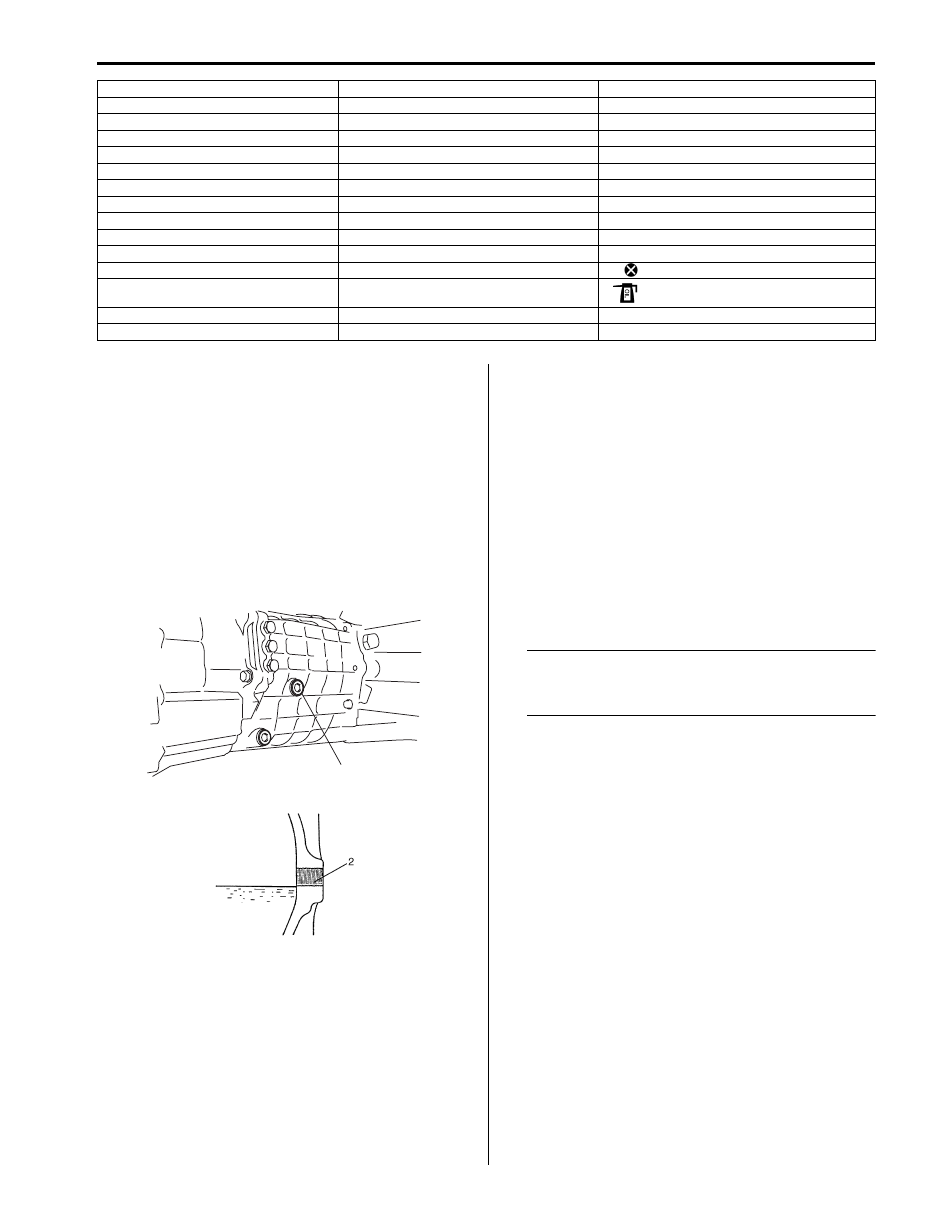
1) Lift up vehicle and check oil leakage.
2) Remove oil level/filler plug (1) with washer and 

check oil level is lower end of oil level/filler plug hole 
(2). If oil is insufficient, pour specified oil up to plug 
hole.

3) Install oil level/filler plug with new washer, and then 

tighten it to specified torque.

Tightening torque
Transmission oil level / filler plug (a):  35 N·m (
3.5 kgf-m, 25.0 lb-ft)

Manual Transmission Oil Change

S5JB0B5206006

1) Before changing oil, be sure to stop engine and lift 

vehicle horizontally.

2) With vehicle lifted up, check leakage. If leakage 

exists, correct or repair it.

3) Remove oil level/filler plug (2) with washer.
4) Remove drain plug (1) with washer, and drain oil.
5) Install drain plug with new washer, and tighten it to 

specified torque.

Tightening torque
Transmission oil drain plug (a):  35 N·m (3.5 kgf-
m, 25.0 lb-ft)

NOTE
If water or rust is mixed in drained oil, be 
sure to check breather hose and boot of 
transmission.


[C]: Countershaft assembly

17. Low speed synchronizer hub circlip

34. Input shaft rear bearing

1. Input shaft front bearing circlip

18. 2nd gear synchronizer ring assembly

35. Input shaft rear bearing circlip

2. Input shaft front bearing

19. Low speed synchronizer sleeve

36. Countershaft front bearing

3. Input shaft

20. Low speed synchronizer hub

37. Countershaft front bearing circlip

4. Input shaft needle bearing

21. 1st gear synchronizer ring assembly

38. Countershaft reduction gear

5. High speed synchronizer hub circlip

22. 1st gear

39. Countershaft high speed gear spacer

6. High speed synchronizer sleeve

23. Low gear needle bearing

40. Countershaft 3rd gear

7. 4th gear synchronizer ring

24. Main shaft

41. Countershaft

8. Synchronizer key

25. Reverse gear needle bearing

42. Countershaft 5th gear

9. Synchronizer key spring

26. Reverse gear

43. Countershaft rear bearing circlip

10. High speed synchronizer hub

27. Reverse gear synchronizer ring

44. Countershaft rear bearing

11. 3rd gear synchronizer ring assembly

28. 5th & reverse synchronizer hub

: Do not reuse.

12. 3rd gear

29. 5th & reverse synchronizer sleeve

: Apply transmission oil.

13. 3rd gear needle bearing

30. 5th & reverse synchronizer hub circlip

14. 3rd gear bush

31. 5th gear needle bearing

1, (a)

I5JB0B520101-01

I5JB0B520102-02

5B-9 Manual Transmission/Transaxle: 

6) Pour new specified oil until oil level reaches bottom 

of oil filler plug hole (3) as shown in figure.

NOTE
It is highly recommended to use API 75 W-90 
gear oil.


Gear oil specifications
: API GL-4 (For SAE classification, refer to 
viscosity chart [A] in figure.)

Manual transmission gear oil capacity
Reference: 2.0 liters (4.2 / 3.5 US / Imp. pt)

7) Install oil level/filler plug with new washer, and then 

tighten it to specified torque.

Tightening torque
Oil filler plug (b):  35 N·m (3.5 kgf-m, 25.0 lb-ft)

Transmission Shift Control Lever Removal and 
Installation

S5JB0B5206007

Fix with bolt type
Removal

1) Remove front console box referring to “Console Box 

Components in Section 9H in related manual”.

2) Lift up boot cover (1), boot (2) and sheet (3).
3) Remove case cover (4) and take out shift control 

lever (5) from gear shift lever case (6).

Installation

1) Tighten new control lever locating bolts (1) to 

specified torque, if removed.

Tightening torque
Control lever locating bolt (a):  10 N·m (1.0 kgf-
m, 7.5 lb-ft)

2) Apply grease to pivot portions and seat, then install 

shift control lever.

“A”:  Grease 99000–25010 (SUZUKI Super 
Grease A)

1, (a)

2, (b)

I5JB0B520006-01

I5JB0A520022-02

80W-90

Temperature

-30

C

o

F

o

-20

-10

0

10

20

30

40

-22

-4

14

32

50

68

86

104

75W-85, 75W-90

[A]

I5JB0A520021-02

6

4

5

3

1

2

I5JB0B520007-01

“A”

1, (a) 

I5JB0B520008-01

Manual Transmission/Transaxle:  5B-10

3) Set shift control lever (2) to gear shift lever case.
4) Install case cover (1) to gear shift lever case (3). 

Tighten case cover bolt to specified torque.

Tightening torque
Case cover bolt (a):  10 N·m (1.0 kgf-m, 7.5 lb-ft)

5) Install sheet, boot (1) with boot cover (2) to floor 

panel.

Tightening torque
Control lever boot cover bolt (a):  12 N·m (1.2 
kgf-m, 9.0 lb-ft)

6) Install front console box referring to “Console Box 

Components in Section 9H in related manual”.

Fix without bolt type
Removal

1) Remove front console box referring to “Console Box 

Components in Section 9H in related manual”.

2) Lift up boots cover (1), boot (2) and sheet (3).
3) With gear shift control case cover (4) pushed down 

with fingers, turn it to counter clockwise and take out 
shift control lever (5).

Installation

1) Tighten new control lever locating bolts (1) to 

specified torque, if removed.

Tightening torque
Control lever locating bolt (a):  10 N·m (1.0 kgf-
m, 7.5 lb-ft)

2) Apply grease to pivot portions and seat, then install 

shift control lever.

“A”:  Grease 99000–25010 (SUZUKI Super 
Grease A)

3) Set shift control lever (2) to gear shift lever case.
4) With gear shift control case cover (1) pushed down 

by hand, turn gear shift control case cover (1) to 
clockwise.

5) Install sheet, boot (1) with boot cover (2) to floor 

panel.

Tightening torque
Control lever boot cover bolt (a):  12 N·m (1.2 
kgf-m, 9.0 lb-ft)

6) Install front console box referring to “Console Box 

Components in Section 9H in related manual”.

(a)

1

2

3

I5JB0B520009-01

2

(a)

1

I5JB0A520027-02

5

2

3

1

4

I5JB0B520111-02

“A”

1, (a) 

I5JB0B520112-01

1

2

I5JB0B520113-01

2

(a)

1

I5JB0A520027-02

5B-11 Manual Transmission/Transaxle: 

Transmission Shift Control Lever Inspection

S5JB0B5206008

• Check transmission shift control lever lower portion 

and control lever locating sheet for excessive wear.

• Check boot for damage. 
Correct or replace if necessary.

Back Up Light Switch Removal and Installation

S5JB0B5206009

Removal

WARNING

!


Refrain from work while exhaust No.2 pipe is 
hot.


NOTE

• When replacing switch, use care not to let 

dust enter transmission through switch 
hole.


1) Hoist vehicle and disconnect connector from back up 

light switch.

2) Remove back up light switch (1), washer and pin 

from transmission front case.

Installation
Reverse removal procedure for installation noting the 
following.
• Apply grease to back up light switch pin (3) and then 

install back up light switch (1), new washer (2) and pin 
to transmission front case.

“A”:  Grease 99000–25010 (SUZUKI Super Grease 
A)

Tightening torque
Back up light switch (a):  39 N·m (3.9 kgf-m, 28.5 
lb-ft)

• Check back up light for proper function with ignition 

switch turned ON and reverse position.

Back Up Light Switch Inspection

S5JB0B5206010

Check back up light switch for function using ohmmeter.
If resistance is not as specified below, replace back up 
light switch.

Back up lamp switch specification
Switch ON (Push): Continuity
Switch OFF (Release): No continuity

1

I5JB0B520010-01

2

1, (a)

3, “A”

I5JB0B520011-01

I5JB0B520012-01


Content   ..  106  107  108  109   ..