Suzuki Grand Vitara JB416 / JB420 (ESP model). Service manual - part 28
 

  Index      Suzuki     Suzuki Grand Vitara JB416 / JB420 ESP model - service and repair manual 2007 year


Search            


Content   ..  26  27  28  29   ..


Suzuki Grand Vitara JB416 / JB420 (ESP model). Service manual - part 28


3C-7 Transfer: Motor-Shift Type (Transfer with Shift Actuator)

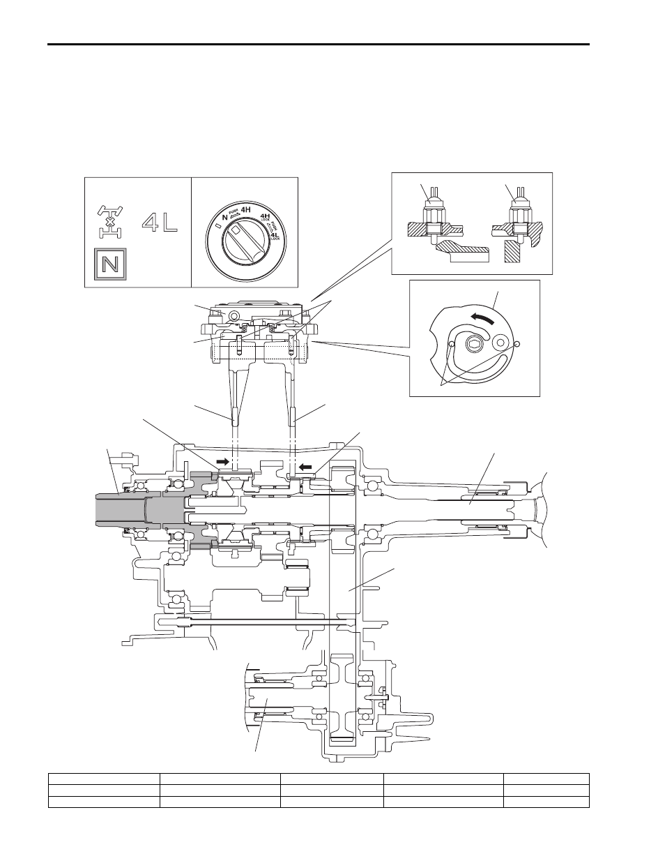
N (Neutral) Position
When N position is selected from 4H position by turning the transfer switch, the transfer shift control actuator motor 
runs and shift cam rotates in the arrow direction “A”. The shift cam shifts the High / Low shift fork in the arrow direction 
“B”, and the reduction shift sleeve moves in the arrow direction “B”. Also, the shift cam shifts the differential lock shift 
fork in the arrow direction “C”, and the differential lock clutch sleeve also moves in the arrow direction “C”.
The driving force from the transmission is transmitted to the transfer input gear. However, as the reduction shift sleeve 
is not engaged with the transfer input gear and low gear, the driving force is not transmitted to the rear output shaft and 
front output shaft.

A

C

B

[A]

[B]

1

2

5

4

4

3

5

9

8

6

7

11

12

13

10

I5JB0A332005-01

[A]: Transfer position indicator 

2. Center differential lock switch

5. Shift cam

8. Input gear

11. Rear output shaft

[B]: Transfer switch

3. Transfer actuator

6. High / Low shift fork

9. Reduction shift sleeve

12. Drive chain

1. 4L/N switch

4. Shift fork pin

7. Differential lock shift fork

10. Differential lock clutch sleeve

13. Front output shaft

Transfer: Motor-Shift Type (Transfer with Shift Actuator) 3C-8

4L-lock (4WD Low Center Differential Lock) Position
When 4L-lock position is selected from 4H-lock position by turning the transfer switch, the transfer shift control 
actuator motor runs and shift cam rotates in the arrow direction “A”. The shift cam shifts the High/Low shift fork in the 
arrow direction “B”, and the reduction shift sleeve moves in the arrow direction “B”. Also, the shift cam shifts the 
differential lock shift fork in the arrow direction “C”, and the differential lock clutch sleeve also moves in the arrow 
direction “C”.
The driving force from the transmission is transmitted from the transfer low gear, through the transfer input gear and 
transfer counter gear with the speed reduced. At this time, as the center LSD case and transfer low gear are engaged 
via reduction shift sleeve, the driving force is transmitted to the rear output shaft.
The driving force of the rear output shaft makes the front output shaft rotate via the differential lock clutch sleeve as in 
the case of 4H-lock position.

A

B

C

[A]

[B]

1

2

5

4

4

3

5

9

8

6

7

11

10

12

13

17

15

18

16

14

19

I5JB0A332006-02

[A]: Transfer position indicator

4. Shift fork pin

9. Reduction shift sleeve

14. Center LSD case

19. Low gear

[B]: Transfer switch

5. Shift cam

10. Differential lock clutch sleeve

15. Front drive shaft

1. 4L/N switch 

6. High / Low shift fork 

11. Front drive sprocket 

16. Counter gear

2. Center differential lock switch

7. Differential lock shift fork

12. Front drive sprocket bush

17. Drive chain

3. Transfer actuator

8. Input gear

13. Rear output shaft

18. Front output shaft

3C-9 Transfer: Motor-Shift Type (Transfer with Shift Actuator)

Input / Output Signal Table of 4WD Control Module

S5JB0E3311008

4WD control module outputs the following signals to actuators, indicators, warning buzzer, according to the transfer 
switch operation.

Output signal (to each component parts)

Transfer 

shift 

actuator

Differential 

lock 

indicator

4L indicator N indicator

Warning 

buzzer

Input signal

Transfer switch

{

{

{

{

{

CPP switch

{

{

{

{

TCM

{

{

{

{

ABS hydraulic unit / control 
module

{

{

{

{

{

4L/N switch

{

{

{

Center differential lock switch

{

{

Transfer: Motor-Shift Type (Transfer with Shift Actuator) 3C-10

On-Board Diagnostic System Description

S5JB0E3311009

For 4WD control system, 4WD control module has the following functions.
• When ignition switch is turned ON with engine at stop, differential lock indicator (1), 4L indicator (2) and N indicator 

(3) turn on at the same time for 2 seconds in order to check operation of these indicators.

• When 4WD control module detects any malfunction in the following area, differential lock indicator (1), 4L indicator 

(2) and N indicator (3) flash continuously and 4WD control module comes into fail-safe mode. For details of fail safe 
mode, refer to “Fail-Safe Table: Motor-Shift Type (Transfer with Shift Actuator)”.
– Transfer switch
– Transfer shift actuator motor
– Transfer shift actuator motor position switch
– 4L/N switch
– Center differential lock switch

• DTC can be checked by either one of the following ways.

– DTC can be checked by using SUZUKI scan tool (4) connected to DLC (5).
– If equipped with diagnosis connector, DTC can be displayed on digital display odometer by shorting diagnosis 

connector (6).

• When 4WD control module detects any malfunction, 4WD control module will shift automatically transfer to either N 

or former position which is in before shifting process began.

DLC (Data Link Connector)
Refer to “Data Link Connector (DLC)” under “On-Board Diagnostic System Description in Section 1A”.

1

2

3

4

5

6

I5JB0A332008-01


Content   ..  26  27  28  29   ..