Suzuki Grand Vitara JB627. Service manual - part 147
 

  Index      Suzuki     Suzuki Grand Vitara JB627 - service and repair manual


Search            


Content   ..  145  146  147  148   ..


Suzuki Grand Vitara JB627. Service manual - part 147


3B-30 Differential: Rear

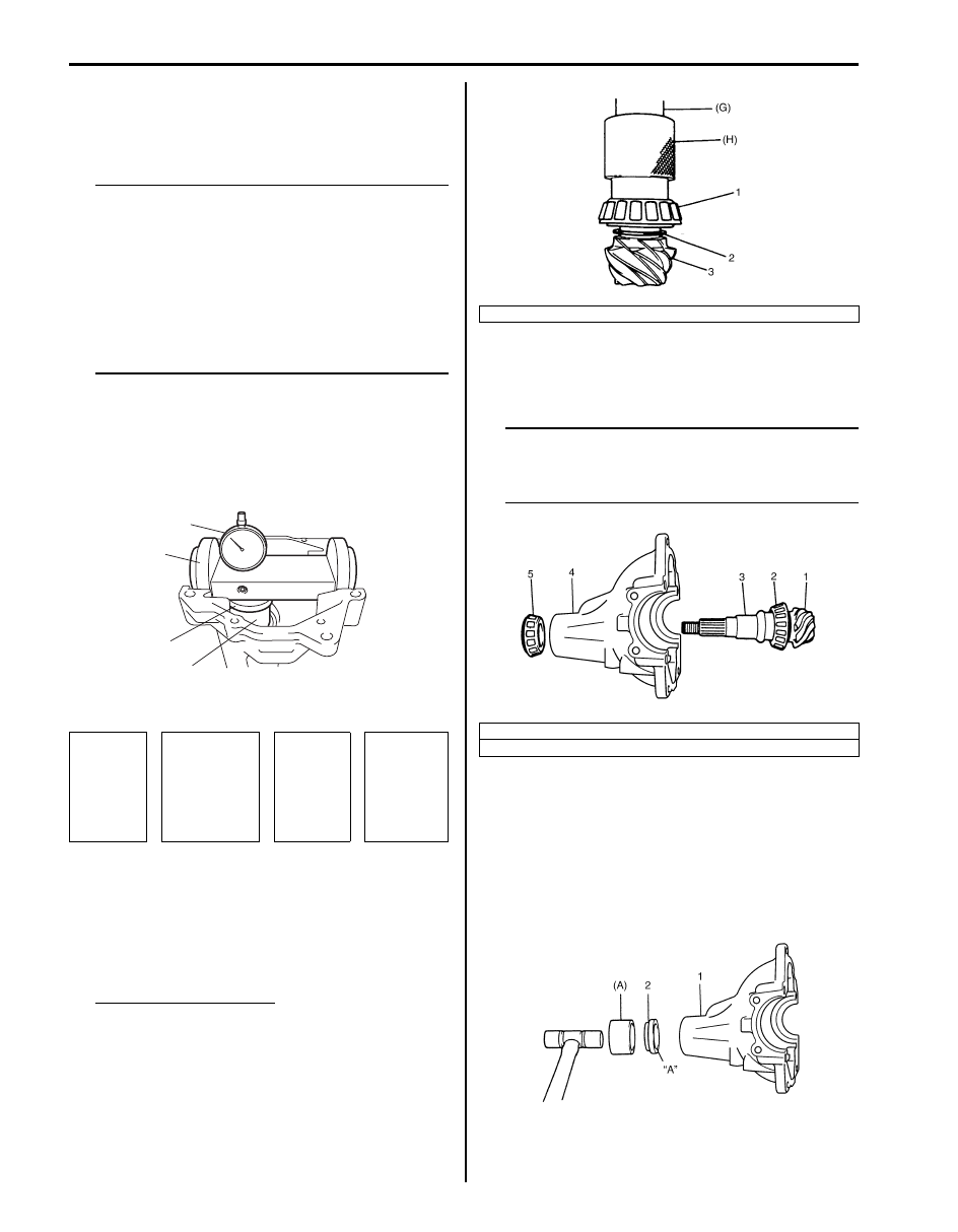
12) Place zero-adjusted mounting dummy and dial 

gauge set on pinion mounting dummy and take 
measurement between zero position and extended 
dial gauge measuring tip.

NOTE

• Repeat turning back and force of dummy 

and measure distance as far as top surface 
of pinion dummy accurately.

• When dial gauge measuring tip extends 

from 0 (zero) position, pointer turns 
counterclockwise.

• Measured value may exceed 1 mm. 

Therefore, it is also necessary to know 
reading of short pointer.


Special tool
(A):  09900–20607
(B):  09926–78311
(D):  09951–16070
(F):  09926–78311–002
:  09922–76520

13) Obtain adjusting shim thickness by the following 

equation.

14) Select adjusting shim(s) (2) closest to calculated 

value from among the following available sizes and 
put it in place and then press-fit rear bearing (1).

Special tool
(G):  09913–85210
(H):  09940–53111

Available shim thickness
1.00, 1.03, 1.06, 1.09, 1.12, 1.15, 1.18, 1.21,1.24, 
1.27, 1.30 and 0.3 mm 
(0.039, 0.040, 0.042, 0.043, 0.044, 0.045, 0.046, 
0.047 0.048, 0.049, 0.050 and 0.012 in.)

15) With new pinion spacer (3) inserted as shown in the 

figure, install front bearing (5) to differential carrier 
(4).

NOTE

• Make sure to use new spacer for 

reinstallation.

• Apply differential oil to bearings.


16) Using special tool and plastic hammer, drive oil seal 

(2) into differential carrier (1) as shown in figure. 
Then apply grease “A” to oil seal lip.

“A”:  Grease 99000–25010 (SUZUKI Super 
Grease A) 

Special tool
(A):  09951–18210

Necessary 

shim 

thickness 

“e”

=

Mounting 

dummy size 

103.0mm /

4.0551 in.           

“a” + “b”

+

Measured 

dimension 

“c”

Drive bevel 

pinion 

mounting 

distance 

102 mm / 

4.0157 in.

(F)

(D)

(B)

(A)

I5JB0A321032-01

3. Drive bevel pinion

1. Drive bevel pinion
2. Rear bearing

I5JB0A321033-01

I5JB0A321034-01

I5JB0A321035-01

Differential: Rear 3B-31

17) While tightening flange nut gradually with special 

tool and power wrench (4 – 10 magnification) (1), set 
preload of pinion to specification.

NOTE

• Before taking measurement with spring 

balance (3) or torque wrench (4), check for 
smooth rotation by hand.

• On measuring preload, rotate the drive 

bevel pinion about 1 rotation per 2 
seconds.

• Be sure to tighten gradually and carefully 

till specified starting torque is obtained. 
Turning back overtightened flange nuts 
should be avoided.


Pinion bearing preload
0.9 – 1.7 N

m (9.0 – 17.0 kg-cm, 7.8 – 14.7 lb-in.)

Spring measure reading with special tool
20 – 40 N (2.0 – 4.0 kg, 4.4 – 8.8 lb)

Special tool
(A):  09922–75222
(B):  09922–66021

18) Select differential side bearing shim as follows.

a) Measure dimension “a” and “b” using vernier 

caliper.

b) Calculate dimension “a” – “b”, and select shims 

from among following available size so that total 
of thickness of right side and left side shims may 
reach the calculated value.

NOTE
Select shims so that thickness of right side 
shims and left side shims become almost 
even.


Available shim thickness
Right side: 1.75, 1.85, 1.95, 2.00, 2.05, 2.15 
and 2.25 mm (0.069, 0.073, 0.077, 0.079, 0.081, 
0.085 and 0.089 in.)
Left side: 2.75, 2.85, 2.95, 3.00, 3.05, 3.15 and 
3.25 mm (0.108, 0.112, 0.116, 0.118, 0.120, 
0.124 and 0.128 in.)

2. Socket wrench

I5JB0A321036-02

I5JB0A321037-04

3B-32 Differential: Rear

19) To measure bevel gear backlash, set dial gauge (1) 

at right angle to bevel gear tooth, fix drive bevel 
pinion and read dial gauge while moving bevel gear.

Special tool
(A):  09900–20607
(B):  09900–20701

Bevel gear backlash
: 0.1 – 0.2 mm (0.004 – 0.008 in.)

NOTE

• Be sure to apply measuring tip of dial 

gauge at right angles to convex side of 
tooth.

• Measure at least 4 points on drive bevel 

gear periphery.

• If backlash exceeds specification given 

below, adjust it by changing thickness 
ratio of differential side bearing shims.


20) Place bearing outer races on their respective 

bearings. Used left and right outer races are not 
interchangeable.

21) Install case assembly (1) in carrier (2).

22) As final step, check gear tooth contact as follows.

a) After cleaning 10 drive bevel gear teeth, paint 

them with gear marking compound evenly by 
using brush (1) or sponge etc.

b) Turn gear to bring its painted part in mesh with 

drive bevel pinion and turn it back and forth by 
hand to repeat their contact.

c) Bring painted part up and check contact pattern, 

referring to the following table. If contact pattern 
is not normal, readjust or replace as necessary 
according to instruction in the table.

NOTE
Be careful not to turn drive bevel gear more 
than one full revolution, for it will hinder 
accurate check.


I5JB0A321038-03

I5JB0A321039-01

A: Paint gear marking compound evenly

1

A

I5JB0A321040-02

Differential: Rear 3B-33

Tooth Contact Pattern

Diagnosis and Remedy

Normal

High Contact
Pinion is positioned too far from the center of drive 
bevel gear (1).
• Increase thickness of pinion (2) height adjusting 

shim and position pinion closer to gear center.

• Adjust drive bevel gear backlash to specification.

Low Contact
Pinion is positioned too close to the center of drive 
bevel gear (1).
• Decrease thickness of pinion (2) height adjusting 

shim and position pinion farther from gear center.

• Adjust drive bevel gear backlash to specification.

If adjustment is impossible, replace differential carrier.

• Check seating of bevel gear or differential case. (Check bevel 

gear for runout.)

• If adjustment is impossible, replace drive bevel gear and pinion 

set or differential carrier.

Replace drive bevel gear and pinion set or differential case.

I5JB0A321041-05

IYSQ01321072-01

IYSQ01321073-01

IYSQ01321074-01

IYSQ01321076-01

IYSQ01321077-01

IYSQ01321078-01

IYSQ01321079-01


Content   ..  145  146  147  148   ..