Suzuki Grand Vitara JB627. Service manual - part 15
 

  Index      Suzuki     Suzuki Grand Vitara JB627 - service and repair manual


Search            


Content   ..  13  14  15  16   ..


Suzuki Grand Vitara JB627. Service manual - part 15


1A-9 Engine General Information and Diagnosis: 

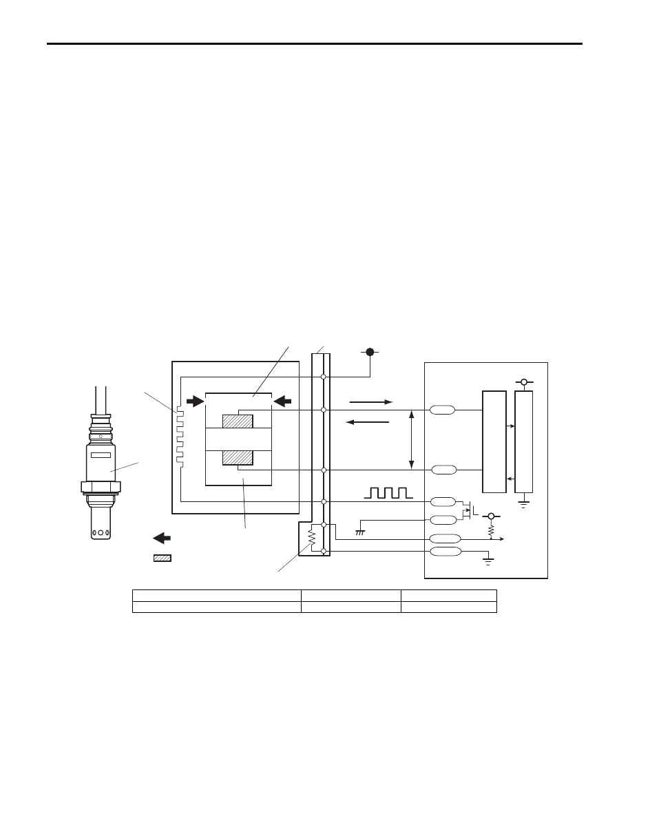
A/F Sensor Description

S6JB0B1101008

A/F sensor (1), in place of the conventional heated Oxygen sensor-1, is installed in the exhaust manifold (bank 1 and 
bank 2) and it consists of a zirconia element (2) which causes the output current to vary according to difference in the 
oxygen concentration, a heater (3) which activates the element and an adjusting resistor (4) (if equipped) which 
adjusts individual difference of the sensor.
A/F sensor detects oxygen concentration in exhaust gas (9) (A/F ratio of the air-fuel mixture) linearly, ranging from 
LEAN to RICH.

Operation
ECM (5) controls the sensor heater (3) and keeps the sensor element temperature at the specified level (about 750 

°C) constantly so that the A/F sensor is activated in the specified way for accurate A/F detection. When the sensor 
element reaches the specified temperature (it is activated), its impedance drops to the specified value (approx. 30 

Ω) 

by its characteristic.
When a certain voltage (about 0.4 V) is applied between sensor elements in this state, circuit current corresponding to 
the sensor element impedance flows in the sensor circuit. ECM detects this circuit current and judges whether the 
sensor is in the active state or not. At this time, sensor current is output linearly in the range of +0.01 mA to +some mA 
on the lean side and –0.01 mA to – some mA on the rich side. The variation in these ranges depends on the difference 
from the stoichiometry A/F ratio, that is, the amount of oxygen between the atmosphere side (6) and exhaust manifold 
(7). According to this sensor output, ECM executes A/F feedback (fuel trim) to achieve the target A/F ratio.
The A/F sensor connector (8) is provided with an adjusting resistor (4) (if equipped) ECM detects the adjusting 
resistance value and corrects the sensor output current value.

AFS-

AFRV

AFRG

AFH+

AFH-

AFS+

5V

5V

12V

1

1

3

7

8

2

6

9

10

5

11

12

13

14

15

4

I6JB0B110001-02

10. Electrode 12. CPU 

14. Rich 

11. A/F signal processing circuit

13. Lean 

15. 0.4 V

Engine General Information and Diagnosis:  1A-10

CAN Communication System Description

S6JB0B1101009

ECM (1), ABS or ESP

® control module (2), TCM (A/T model) (3), BCM (4), 4WD control module (if equipped) (5), 

combination meter (6), keyless start control module (if equipped) (7) and steering angle sensor (8) (ESP

® model) of 

this vehicle communicate control data between each control module.
Communication of each control module is established by CAN (Controller Area Network) communication system.

CAN communication system uses the serial communication in which data is transmitted at a high speed. if uses a 
twisted pair of two communication lines for the high-speed data transmission. As one of its characteristics, multiple 
control modules can communicate simultaneously. In addition, it has a function to detect a communication error 
automatically. Each module reads necessary data from the received data and transmits data. ECM communicates 
control data with each control module as follows.

1

3

4

5

7

8

2

6

I6JB01110110-02

1A-11 Engine General Information and Diagnosis: 

ECM Transmission Data

NOTE
In communication between ECM and combination meter, between ECM and keyless start control 
module (if equipped) and between ECM and 4WD control module (if equipped), data is transmitted only 
from ECM to combination meter, keyless start control module (if equipped) and 4WD control module (if 
equipped). (Combination meter, keyless start control module (if equipped) and 4WD control module (if 
equipped) does not transmit data to ECM.)


Engine torque signal

Accelerator pedal position

Engine speed

Throttle position 

Stand by to engage air

conditioning compressor

Top gear inhibit

Torque converter clutch

control inhibit

Lock up / slip control

inhibit signal

Immobilizer indication

Engine emissions 

related malfunction

Engine coolant

temperature

Fuel level percent

Cruise control signal

(if equipped)

Cruise control system

indication (if equipped)

Vehicle speed

Brake pedal switch 

active

Air conditioning

compressor clutch

engaged

(if equipped with A/C)

Distance kilometers per 

liter of fuel

TCM
(A/T 

model)

BCM

Transmits data

of ECM

4WD

control

module

(if 

equipped)

Combination 

Meter

Keyless Start

 Control Module

(if equipped)

ESP® Control 

Module (if equipped)

ABS

Hydrauric

Unit/Control

Module

Assembly 

(if equipped)

I6JB0B110002-01

Engine General Information and Diagnosis:  1A-12

ECM Reception Data

TCM

(A/T model)

BCM

ESP® Control 

module (if equipped)

4WD control module 

(if equipped)

Torque reduction request

Slip control signal

Transmission malfunction

indication on

Transmission emissions related

malfunction active

Transmission gear selector

position

Daytime running light active

(if equipped with DRL)

Air conditioning switch ON

(if equipped with A/C)

A/T mode status

Electric load active (low beam)

Electric load active (high beam)

Electric load active (tail light)

Electric load active (rear defogger)

Blower fan step

Torque up request

Torque request rolling count

Wheel speed pulse (rear right)

Wheel speed pulse (rear left)

Antilock brake system active

Electronic stability program 

system active

Electronic stability program

system OFF

4WD shift position

ABS hydraulic

unit/control module

assmbly (if equipped)

Transmits data of ECM

I6JB0B110003-01


Content   ..  13  14  15  16   ..