SsangYong Stavic / SsangYong Rodius (2005 year). Service manual - part 9
 

  Index      SsangYong     SsangYong Stavic / SsangYong Rodius - service and repair manual 2005 year


Search            


Content   ..  7  8  9  10   ..


SsangYong Stavic / SsangYong Rodius (2005 year). Service manual - part 9


1B-15

CHANGED BY

EFFECTIVE DATE

AFFECTED VIN

ENGINE MECHANICAL

M162 GSL ENG SM - 2005.7

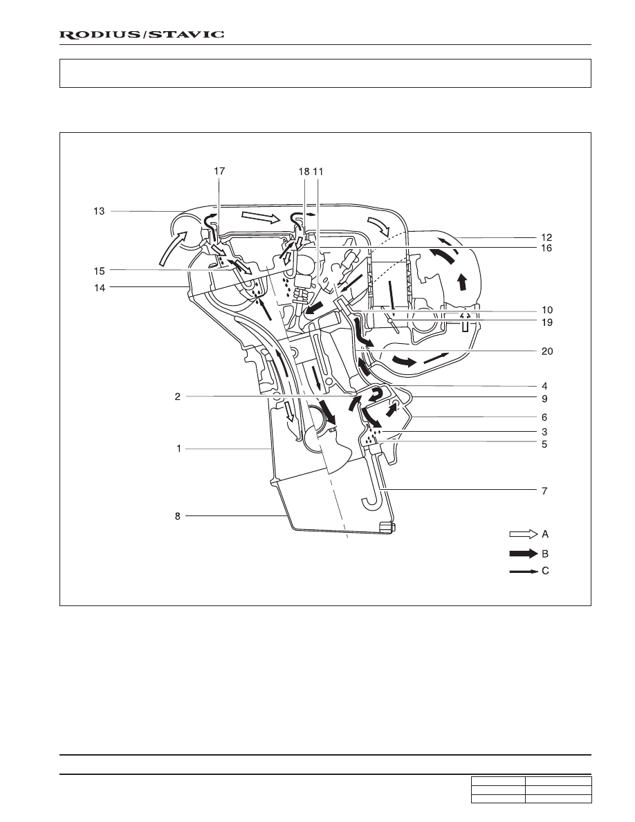
CRANKCASE VENTILATION SYSTEM

CRANK CASE AND CYLINDER HEAD

1. Crankcase

2. Air admission port in crankcase

3. Oil drain port

4. Filter

5. Gasket

6. A/C bracket

7. Oil drain pipe

8. Oil pan

9. Air admission line

10. Vent line

11. Restriction hole (diameter = 2 mm)

12. Intake manifold

13. Intake air duct (cross pipe)

14. Cylinder head cover

15. Oil separator

16. Oil separator

17. Air admission and vent connection

18. Air admission and vent connection

19. Throttle valve

20. Vent line

A. Fresh air

B. Blowby gas in partial load

C. Blowby gas in full load

1B-16

CHANGED BY

EFFECTIVE DATE

AFFECTED VIN

ENGINE MECHANICAL

M162 GSL ENG SM - 2005.7

Operation at Idling and Mid-Load

• It show that the throttle valve (19) is closed or very partially

opened and the vacuum pressure in intake manifold is high.

The blowby gas in the crankcase in partial load flows into
the intake manifold through the vent line (20) after passing
the air conditioner bracket (6) and the filter (4). The air
reentered into the intake manifold will be dilluted on the
flow through the restriction hole (11) in the vent line (10).

The circulated engine oil is separated at the air conditioner
bracket (6) and then returns into the oil pan through the
drain pipe (7).

The vacuum pressure generated at the crankcase sucks
fresh air from intake air line (13) through the air admission
and vent connection (17, 18).

The fresh air prevents engine oil from being contaminated
and the air admission and vent connection (17, 18) is
designed to control the rapid pressure changes in intake
air line (13).

Operation at Full-Load

• The throttle valve (19) is fully opened.

All the blowby gases flow into the intake air duct (13) after
passing through the oil separator (15, 16) of the cylinder
head cover (14) when fully loaded. This dilluted air will be
supplied to the combustion chamber through the intake
manifold (12).

1B-17

CHANGED BY

EFFECTIVE DATE

AFFECTED VIN

ENGINE MECHANICAL

M162 GSL ENG SM - 2005.7

ALTERNATOR

1. Nut  (M8) ............ 22.5 ~ 27.5 Nm (16.5 ~ 20.5 lb-ft)

2. Bolt (M8 x 30, 3 pieces)

............................ 22.5 ~ 27.5 Nm (16.5 ~ 20.5 lb-ft)

3. Bolt (M8 x 40, 1 piece)

............................ 22.5 ~ 27.5 Nm (16.5 ~ 20.5 lb-ft)

4. Bolt (M8 x 70, 1 piece)

............................ 22.5 ~ 27.5 Nm (16.5 ~ 20.5 lb-ft)

5. Bolt (M8 x 75, 1 piece)

............................ 22.5 ~ 27.5 Nm (16.5 ~ 20.5 lb-ft)

Removal & Installation Procedure

1. Remove the drive belt.

2. Remove the alternator.

3. Unscrew the alternator carrier bolts and remove the

carrier.

Installation Notice

4. Installation should follow the removal procedure in the

reverse order.

Tightening torque

25 Nm (18 lb-ft)

1B-18

CHANGED BY

EFFECTIVE DATE

AFFECTED VIN

ENGINE MECHANICAL

M162 GSL ENG SM - 2005.7

POWER STEERING PUMP AND A/C BRACKET

Preceding Work: Removal of cooling fan and shroud

1. Vent hose

2. Bolt (M8 x 91, 2 pieces)

............................ 22.5 ~ 27.5 Nm (16.5 ~ 20.5 lb-ft)

3. Power steering pump

4. Bolt (M8 x 105, 4 pieces)

............................ 22.5 ~ 27.5 Nm (16.5 ~ 20.5 lb-ft)

5. Washer

6. A/C compressor

7. Bolt (M8 x 40, 3 pieces, M8 x 95, 2 pieces)

............................ 22.5 ~ 27.5 Nm (16.5 ~ 20.5 lb-ft)

8. A/C bracket

9. Gasket .......................................................... Replace

10. Bracket

11. Bolt (M8 x 22, 2 pieces)

............................ 22.5 ~ 27.5 Nm (16.5 ~ 20.5 lb-ft)

12. Tensioning pulley

13. Nut ...................... 40.5 ~ 49.5 Nm (29.9 ~ 36.5 lb-ft)


Content   ..  7  8  9  10   ..