SsangYong Actyon Sports II. Service manual - part 170
 

  Index      SsangYong     SsangYong Actyon Sports II - service and repair manual 2012-2013 year


Search            


Content   ..  168  169  170  171   ..


SsangYong Actyon Sports II. Service manual - part 170


14-16

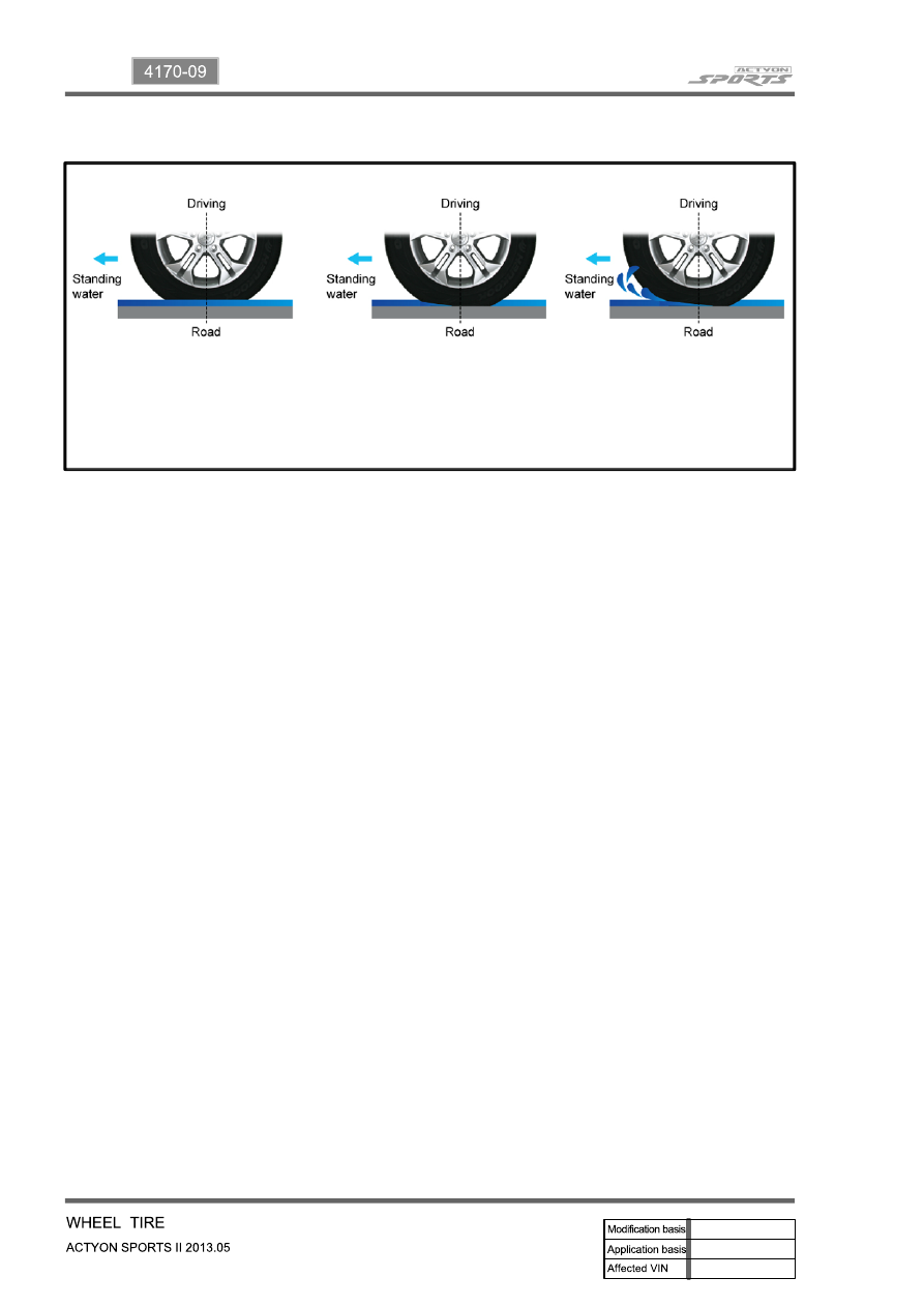
When the vehicle is driven on a road surface covered with water at high speed, tires do not contact with 

the road surface but rotate floating on a thin film of water.

It causes brake failure, lower traction force and losing the steering performance. 

To prevent this, increase the tire inflation pressure, use tires with leaf shape tread which is not worn. 

However, it is a best measure to drive slowly. 

Hydro Planing

Vehicle speed ≤ 60 km/h

No Hydro planning

Vehicle speed = 80 km/h

Partial Hydro planning

Vehicle speed ≥ 100 km/h

Full Hydro planing

14-17

4170-09

If weight is not equally distributed around the wheel, unbalance centrifugal force by the wheel rotation 

produces vibration. As the centrifugal force is produced proportional to the square of the rotating speed, 

the wheel weight should be balanced even at high speed. There are two types of the tire and wheel 

balancing: static and dynamic. Abnormal vibration may also occur due to unbalanced rigidity or size of 

tires.

Static Balance

When the free rotation of the wheel is allowed, 

the heavier part is stopped on the bottom if the 

wheel weight is unbalanced and this is called 

"Static Unbalance". Also, the state at which tire's 

stop position is not same is called "Static 

Balance" when the wheel is rotated again. If the 

part A is heavier as shown in the figure 1, add 

the balance weight of a weight corresponding to 

unbalanced weight from B to A to maintain the 

static balance. If the static balance is not 

maintained, tramping, up and down vibration of 

the wheels, occurs. 

Dynamic Balance

The static unbalance of the wheel creates the 

vibration in the vertical direction, but the dynamic 

unbalance creates the vibration in the lateral 

direction. As shown in the figure 2 (a), if two 

parts, (2) and (3), are heavier when the wheels 

are under the static balance condition, dynamic 

unbalance is created, resulting in shimmy, left 

and right vibration of the wheels, and the torque 

Fxa is applied in the axial direction. To correct 

the dynamic unbalance, add the balance weight 

of a same weight for two points of  the 

circumference of the rim, A and B, as shown in 

the figure 2 (b), and apply the torque in the 

opposite direction to the torque Fxa to offset in 

order to ensure smooth rotation of the wheel. 

Center

A

B

(a) (b) 

[Figure 1]

[Figure 2]

3. WHEEL BALANCE

14-18

4. WHEEL ALIGNMENT

▶Toe-in

▶Camber

In automotive engineering, toe, also known as 

tracking, is the symmetric angle that each wheel 

makes with the longitudinal axis of the vehicle, as a 

function of static geometry, and kinematic and 

compliant effects. This can be contrasted with 

steer, which is the anti-symmetric angle, i.e. both 

wheels point to the left or right, in parallel (roughly). 

Positive toe, or toe in, is the front of the wheel 

pointing in towards the center line of the vehicle. 

Negative toe, or toe out, is the front of the wheel 

pointing away from the center line of the vehicle. 

Toe can be measured in linear units, at the front of 

the tire, or as an angular deflection.

Camber is the angle made by the wheels of a 

vehicle; specifically, it is the angle between the 

vertical axis of the wheels used for steering and 

the vertical axis of the vehicle when viewed from 

the front or rear. It is used in the design of steering 

and suspension. If the top of the wheel is farther 

out than the bottom (that is, away from the axle), it 

is called positive camber; if the bottom of the 

wheel is farther out than the top, it is called 

negative camber.

Wheel alignment consists of adjusting the angles of the wheels so that they are parallel to each other 

and perpendicular to the ground, thus maximizing tire life and ensures straight and true tracking along a 

straight and level road.

Camber angle alters the handling qualities of a particular suspension design; in particular, negative 

camber improves grip when cornering. This is because it places the tire at a better angle to the road, 

transmitting the forces through the vertical plane of the tire rather than through a shear force across it. 

Another reason for negative camber is that a rubber tire tends to roll on itself while cornering. Negative 

camber can also be caused by excessive weight on the front wheels. This is commonly seen on 

modified cars with larger engines than standard; the weight of the modified engine can make the wheels 

negatively camber. The inside edge of the contact patch would begin to lift off of the ground if the tire had 

zero camber, reducing the area of the contact patch. This effect is compensated for by applying negative 

camber, maximizing the contact patch area. Note that this is only true for the outside tire during the turn; 

the inside tire would benefit most from positive camber.

14-19

4170-09

▶Caster

Caster is the angle to which the steering pivot 

axis is tilted forward or rearward from vertical, as 

viewed from the side. If the pivot axis is tilted 

backward (that is, the top pivot is positioned 

farther rearward than the bottom pivot), then the 

caster is positive; if it's tilted forward, then the 

caster is negative.

Positive caster tends to straighten the wheel 

when the vehicle is traveling forward, and thus is 

used to enhance straight-line stability. The 

mechanism that causes this tendency is clearly 

illustrated by the castering front wheels of a 

vehicle. The steering axis of a vehicle wheel is 

set forward of where the wheel contacts the 

ground. As the vehicle is driving forward, the 

steering axis pulls the wheel along, and since the 

wheel drags along the ground, it falls directly in 

line behind the steering axis. The force that 

causes the wheel to follow the steering axis is 

proportional to the distance between the steering 

axis and the wheel-to-ground contact patch-the 

greater the distance, the greater the force. This 

distance is referred to as "trail."


Content   ..  168  169  170  171   ..