Seat Leon (2023 year). Manual in english - page 11
 

  Index      Manuals     Seat Leon (2023 year). Manual in english


Search            copyright infringement  


Content      ..     9      10      11      12     ..


Seat Leon (2023 year). Manual in english - page 11


Checking and refilling levels

333

Windscreen washer reservoir

However, if the brake fluid level goes down no-
ticeably in a short time, or drops below the 
mark, there may be a leak in the brake system.
Seek specialist assistance. A warning light on
the instrument panel display monitors the brake
fluid level.

 Brake fluid level

The control lamp lights up red.
Brake fluid level is too low.

 Stop driving!

Check the brake fluid level.

If the brake fluid level is too low, seek special-

ist assistance.

Changing brake fluid

We recommend that you have the brake fluid
changed by a Technical Service.

WARNING

If the brake fluid level is low or unsuitable/old
brake fluid is used, the brake system may fail
or braking power may be reduced.

Check the brake system and the brake fluid

level regularly!

When the brake fluid is used and brakes

are subjected to extreme braking forces,
bubbles of vapour form in the brake system.
These bubbles can significantly reduce brak-

ing power, notably increasing braking dis-
tance, and could result in the total failure of
the brake system.

Be sure to always use the correct brake

fluid. Only use brake fluid that expressly
meets the VW 501 14 standard.

You can buy VW 501 14 standard brake

fluid in a SEAT dealership or a SEAT Offi-
cial Service. If none is available, use only
high-quality brake fluid that meets DIN ISO
4925 CLASS 4 standards, or USA Standards
FMVSS 116 DOT 4.

The replacement brake fluid must be new.

Brake fluid should be stored in the closed

original container in a safe place out of
reach of children. Risk of poisoning!

NOTICE

Brake fluid should not come into contact with
the vehicle paintwork, as it is abrasive.

Note

Brake fluid is an environmental pollutant.
Collect any spilt service fluids and allow a
professional to dispose of them.

Windscreen washer reser-
voir

Checking the level of the window
washer tank and refilling it

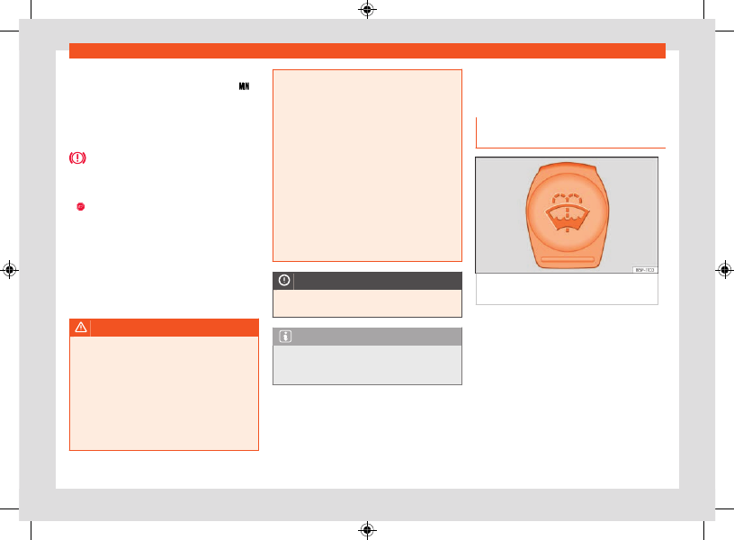
Fig. 225 

In the engine compartment: blue cap

of the windscreen washer tank.

Check the water level in the windscreen washer
reservoir regularly and top up as required.
The window washer tank contains liquid deter-
gent for the windscreen and rear window.
There is a sieve in the filler neck of the washer
fluid tank. When filling the tank, this sieve re-
tains large dirt particles so that they do not
reach the nozzles. Do not remove the sieve ex-
cept for cleaning. If the sieve is damaged or
not fitted, these dirt particles could enter the
system during filling and clog the windscreen
washer nozzles.

CarManuals2.com

334

Checking and refilling levels

Raise the bonnet 

››› 

 on page 326

.

The windscreen washer reservoir is marked

with the symbol   on the cap.

 Check if there is enough fluid in the tank.

Plain water is not enough to clean the wind-
screen and headlights. We recommend that
you always add a product to the windscreen
washer fluid.

Recommended windscreen wipers

For the hottest seasons we recommend sum-

mer G 052 184 A1 for clear glass. Proportions of
the mixture in the washer fluid tank: 1:100 (1 part
concentrate per 100 parts water).

All year round, G 052 164 A2 for clear glass.

Approximate proportion of the winter mixture,
up to -18°C (0°F): 1:2 (1 part concentrate per
2 parts water); otherwise, a 1:4 proportion of
mixture in the washer fluid tank.

The capacity of the windscreen washer tank is
approximately 3 litres.

NOTICE

If the water from the windscreen washer
does not contain enough anti-freeze, it may
freeze on the windscreen and rear window,
reducing forward and rear visibility.

In winter, ensure the windscreen washer

contains enough anti-freeze.

In cold conditions, you should not use the

windscreen wiper system unless you have
warmed the windscreen with the ventilation
system. The antifreeze could freeze on the
windscreen and reduce visibility.

NOTICE

Never mix an unsuitable antifreeze or other
similar additives with the windscreen washer
water. A greasy layer may be formed on the
windscreen which will impair visibility.

Use clean water with a window cleaner

recommended by SEAT.

If necessary, add a suitable antifreeze to

the water in the reservoir.

NOTICE

Do not mix cleaning products recommen-

ded by SEAT with other products. This could
lead to flocculation and may block the wind-
screen washer jets.

When topping up service fluids, make ab-

solutely certain that you fill the fluids into
the correct reservoirs. Using the wrong fluids
could cause serious malfunctions.

Lack of window washer fluid causes the

view through the windscreen to be obscured.

Engine oil

General notes

Fig. 226 

In the engine compartment: engine

oil label

CarManuals2.com

Checking and refilling levels

335

Engine oil

A

B

Fig. 227 

In the engine compartment: area

where the engine oil label is located

Key to the 

››› 

Fig. 226

:

Information about the engine oil standard.
Information about engine oil viscosity.

The engine comes with a special, multi-grade
oil that can be used all year round.
Because the use of high-quality oil is essential
for the correct operation of the engine and its
long useful life, when topping up or changing
oil, use only those oils that comply with VW
standards.

For vehicles with an engine oil label

If the engine oil has to be topped up, use one
of the oils shown on the label 

››› 

Fig. 226

. The

label with the prescribed standard is located at
the front of the engine compartment 

››› 

Fig. 227

1

. If you use the recommended engine oil, you

can top up the oil as often as necessary.

For vehicles without an engine oil label

Contact a specialised workshop or SEAT of-
ficial service for information about the corre-
sponding standard.

If the engine oil level is too low

If the recommended engine oil is not availa-
ble, 

in the event of an emergency

 you can

change the oil 

once

 with a maximum of 0.5 l of

the next oil until the next oil change:

Petrol engines:

 standard VW 504 00,

ACEA C3, ACEA C4, API SN or IL-
SAC GF-6A.

CNG engines:

 standard VW 504 00,

ACEA C3, ACEA C4, API SN or IL-
SAC GF-6A.

Diesel engines:

 standard VW 507 00,

ACEA C3, ACEA C4 or API CK-4.

SEAT recommends changing the oil at a speci-
alised workshop. SEAT recommends an Official
SEAT Service.

NOTICE

SEAT recommends the use of engine oils
approved according to the appropriate VW
standard. Use of engine oils that do not meet
these quality requirements can cause engine
damage.

SEAT recommends the use of Original SEAT
Spare Part engine oils.

Engine oil additives

No type of additive should be mixed with the
engine oil. The deterioration caused by these
additives is not covered by the warranty.

NOTICE

0.5 l of engine oil of one of the indicated en-
gine oil standards may be used, only in the
event of an emergency and in exceptional
cases.

NOTICE

Take the following into account if you have
refilled with an engine oil different to those
specified in the aforementioned standards,
or by your SEAT technical service centre:

 There is no way of completely avoiding the

danger of causing damage to the engine and
particulate filter.

You can continue driving with the vehicle if

the refill was no more than 0.5 l of engine
oil. Go to a specialised workshop as soon
as possible and request an oil change. Oth-
erwise, there is a danger of engine damage.

If you have topped up more than 0.5 l of

engine oil, drive with the engine at low load
levels and within the medium RPM range as a
maximum. Do not drive at more than 80 km/h
and do not travel more than 300 km (approx-
imately). Go to a specialised workshop as
soon as possible and request an oil change.
Otherwise, there is a danger of engine dam-
age.

CarManuals2.com

336

Checking and refilling levels

A

B

C

You are responsible for the risk of possible

damage to the vehicle (engine, exhaust sys-
tem). If in doubt, do not start the engine and
request assistance from the technical serv-
ice centre.

Do not start the engine if you have topped

up with a fluid other than engine oil. Request
assistance from the technical service centre.
Danger of engine damage!

Note

Before a long trip, we recommend finding an
engine oil that conforms to the correspond-
ing VW specifications and recommend keep-
ing it in the vehicle. This way, the correct en-
gine oil will always be available for a top-up
if needed.

If the label showing the engine oil specifi-

cations is missing 

››› 

Fig. 226

, please con-

tact a specialist workshop.

Checking and topping up the engine
oil level

Fig. 228 

Engine oil dipstick.

Fig. 229 

Oil filler cap cover in the engine

compartment.

Key to the 

››› 

Fig. 228

:

Do not top up oil in any case.
You can add oil but keep the level in that
zone.

The oil level is too low. Add oil up to zone

B

.

Before opening the bonnet, read and observe
the warnings 

››› 

page 326, 

Working in the en-

gine compartment

.

Check the oil level

The engine oil dipstick indicates the level of the
oil.

 Park the vehicle in a horizontal position.

Briefly run the engine at idle speed until the

operating temperature is reached and then
stop.

Wait for about two minutes.

Locate the oil level dipstick. It can be recog-

nized by its coloured upper end.

Pull out the dipstick. Wipe the dipstick with a

clean cloth and insert it again, pushing it in as
far as it will go.

Then pull it out again and check the oil level 

››› 

Fig. 228

. Top up with engine oil if necessary.

The oil should leave a mark between the areas

A

 and 

C

. It must never exceed zone 

A

.

Depending on how you drive and the conditions
in which the vehicle is used, oil consumption
can be up to 0.5 l/1000 km. Oil consumption
is likely to be higher for the first 5,000 km. For
this reason the engine oil level must be checked
at regular intervals, preferably when filling the
tank and before a journey.

CarManuals2.com

Checking and refilling levels

337

Engine oil

Topping up engine oil

Locate the engine oil filler cap. It can be

recognized by the symbol 

 on the cover 

››› 

Fig. 229

.

 Unscrew cap from the oil filler mouth 

››› 

Fig. 229

.

Carefully add oil in small quantities (no more

than 0.5 l).

To avoid adding too much oil, whenever you

add a certain amount, wait about 2 minutes
and recheck the oil level 

››› 

page 336

.

If necessary, add some more oil.

When the oil level reaches at least zone 

››› 

Fig. 228


B

, carefully screw on the engine

oil filler cap 

››› 

.

Engine oil specification 

››› 

page 334

.

WARNING

Any work carried out in the engine compart-
ment or on the engine must be carried out
cautiously.

 When working in the engine compart-

ment, always observe the safety warnings 

››› 

page 326

.

WARNING

Oil is highly inflammable! Ensure that no oil
comes into contact with hot engine compo-
nents when topping up.

NOTICE

If the oil level is above zone 

A

, do not start

the engine. This could result in damage to
the engine and catalytic converter. Contact
a Technical Service.

For the sake of the environment

Under no circumstances should the oil level
be above zone 

A

. Otherwise oil can be

drawn in through the crankcase breather and
leak into the atmosphere via the exhaust sys-
tem.

Note

Before a long trip, we recommend finding an
engine oil that conforms to the correspond-
ing VW specifications and recommend keep-
ing it in the vehicle. This way, the correct en-
gine oil will always be available for a top-up
if needed.

Engine oil change

We recommend that you have the engine oil
changed by a Technical Service.

WARNING

Only change the engine oil yourself if you
have the specialist knowledge required!

Before opening the bonnet, read and ob-

serve the warnings 

››› 

page 326

.

Wait for the engine to cool down. Hot oil

may cause burn injuries.

Wear eye protection to avoid injuries, such

as acid burns, caused by splashes of oil.

When removing the oil drain plug with your

fingers, keep your arm horizontal to help pre-
vent oil from running down your arm.

Wash your skin thoroughly if it comes into

contact with engine oil.

Engine oil is poisonous! Used oil must be

stored in a safe place out of the reach of
children.

NOTICE

No additives should be used with engine
oil. This could result in engine damage. Any
damage caused by the use of such additives
would not be covered by the factory war-
ranty.

CarManuals2.com

338

Checking and refilling levels

For the sake of the environment

We recommend that you change the en-

gine oil and the filter at a technical service
centre.

Never pour oil down drains or into the

ground.

Use a suitable container when draining the

used oil. It must be large enough to hold all
the engine oil.

Troubleshooting

 Engine oil pressure too low

The indicator lamp lights up red.


Do not carry on driving!

 Switch off the en-

gine. Check the engine oil level.

 If this warning lamp 

 starts to flash, and

is accompanied by 

three audible warnings

,

switch off the engine and check the oil level. If
necessary, add more oil 

››› 

page 336

.

If the warning lamp 

 flashes although the

oil level is correct, 

stop driving

. Do not even

run the engine at idle speed! Seek professional
assistance.

 Engine oil level too low

The indicator lamp lights up yellow.

Check the engine oil level as soon as possible 

››› 

page 336

.

Change the oil as soon as you have the op-

portunity to do so.

 Fault in the oil level sensor

The control lamp flashes yellow.

 Have the check done by a specialised work-

shop.

Until then it is advisable to check the oil level

every time you refuel.

12-volt battery

Introduction

The 12 volt battery is located in the engine
compartment or in the luggage compartment
(PHEV hybrid vehicles). The 12 volt battery is
checked and, if necessary, replaced as part of
maintenance work.

All work on batteries requires specialist knowl-
edge. Please refer to a SEAT Official Service
or a workshop specialising in batteries: risk of
burns or exploding battery!

The battery must not be opened! 

Never try to

change the fluid level of the battery. Otherwise
explosive gas is released from the battery that
could cause an explosion.

Battery warning indications

Wear protective goggles.

Battery acid is extremely corrosive. Wear
protective gloves and eye protection.
Rinse any splashes of electrolyte with

plenty of water.

Fires, sparks, open flames and smoking
are prohibited.

The battery should only be charged in a
well-ventilated zone. Risk of explosion!

Keep children away from acid and the
battery.
Always follow the instruction manual.

If the vehicle is not used for long periods

The vehicle has a system for monitoring
the current consumption when the engine
is left unused for extended periods of time 

››› 

page 344

. Some functions, such as the in-

terior lights, or the remote door opening, may
be temporarily disabled to prevent the battery
from running flat. These functions will come
back on as soon as the ignition is switched on
and the engine started.

CarManuals2.com

Checking and refilling levels

339

12-volt battery

WARNING

Working on the 12-volt battery and electri-
cal system can cause severe burns, fire and
electric shock. Always read and observe the
following warnings and safety precautions
before working on the battery:

Before working on the 12-volt battery,

switch off the ignition and all electrical con-
sumers and disconnect the negative cable
from this battery.

Always keep children away from the 12-volt

battery electrolyte and the battery itself.

Always wear eye protection and protective

gloves.

The battery electrolyte is very corrosive It

can cause skin burns and blindness. When
handling the 12-volt battery, protect your
hands, arms and face in particular from acid
splashes

Do not smoke while working and never

work in the vicinity of naked flames or sparks.

Avoid sparks caused by electrostatic dis-

charges, just like when handling electric ca-
bles and devices.

Never short the battery terminals.

Never use damaged 12-volt batteries. They

could explode. If the 12-volt battery is dam-
aged, replace it immediately.

Never use a frozen 12 volt battery. When

the battery is discharged, it may freeze at
temperatures close to 0°C (+32 °F). If the 12-
volt battery is frozen, replace it immediately.

NOTICE

Do not expose the 12-volt battery to direct
sunlight for a prolonged period of time.

Ultraviolet rays can damage the battery

casing.

NOTICE

If the vehicle is not to be used for a long pe-
riod of time, protect the 12-volt battery from
frost.

The battery may freeze and, as a result,

suffer irreparable damage.

Note

After starting the engine with a deeply dis-
charged or newly replaced 12-volt battery,
or after a jump start, some system settings
(time, date, personalised comfort settings
and programs) may be incorrectly set or de-
leted. Check and correct these settings once
the battery is sufficiently charged.

Note

During the winter, the starting power may
be reduced, and if necessary, the battery
should be charged.

Check the electrolyte level

Fig. 230 

Hybrid vehicles (PHEV): location of

the battery in the luggage compartment

Fig. 231 

Sight glass on the top of the 12 volt

battery (schematic representation).

Access to the 12 volt battery

The 12-volt battery is located in the engine
compartment (conventional vehicles) or under
the luggage compartment floor (PHEV hybrid
vehicles).

CarManuals2.com

340

Checking and refilling levels

Yellow or colourless:

Black:

Valid for conventional and Mild Hybrid vehicles:

 Raise the bonnet 

››› 

 in 

Working in the

engine compartment

 on page 326

.

Lift the cover that protects the front of the

battery.

Valid for hybrid vehicles (PHEV):

 Open the luggage compartment.

Raise the floor of the luggage compartment 

››› 

page 284

 to gain access to the 12-volt bat-

tery cover 

››› 

Fig. 231

.

A suitable tool must be used to open and

close the cover.

Check the level

The electrolyte level should be checked regu-
larly in high-mileage vehicles, in hot countries
and in older batteries.

 Check the colour display in the sight glass on

the top of the battery 

››› 

Fig. 231

.

 If there are air bubbles in the window, tap the

window gently until they disperse.
The “magic eye” indicator, located on the top
of the battery changes colour, depending on
the charge state and electrolyte level of the
battery.
There are two different colours:

The battery's electrolyte

level is too low. Go to a specialised work-
shop to have the battery checked and re-
placed if necessary.

The battery’s electrolyte level is correct.

Charging, replacing, disconnecting
and connecting the 12-volt battery

If you suspect that the 12-volt battery is dam-
aged or defective, have it checked by a quali-
fied specialist workshop.

Charging the 12-volt battery

Contact a specialist workshop for charging the
12-volt battery, as the battery model fitted in
the vehicle in the factory uses a technology
that requires limited voltage charging 

››› 

.

SEAT recommends visiting a SEAT dealership
for this.

Replacing the 12-volt battery

The 12-volt vehicle battery has been designed
to suit its location and has special safety fea-
tures. If a 12 volt battery needs to be replaced,
the replacement battery must be installed by
a qualified technician. SEAT recommends visit-
ing a SEAT dealership. Component information
regarding size, maintenance, power and safety
characteristics to be met can be obtained from
a qualified technician, who should have the
necessary documentation and technical equip-
ment. SEAT recommends visiting a SEAT deal-
ership.

The degassing hole of the 12 volt battery must
always be on side of the negative pole. The
degassing hole on the side of the positive pole
must always be sealed.
Only use maintenance-free 12 volt batteries
that comply with the TL 825 06 and VW 7 50 73
standards. These standards must be dated Oc-
tober 2014 or later.
The 12 volt battery must always be replaced
by a qualified technician, as the vehicle's elec-
tronic system must also be adjusted as part
of the replacement. In addition, the battery pa-
rameters relating to operational safety can only
be determined with the original battery. Only a
qualified technician has both the right technol-
ogy to make the adjustment and the correct
replacement batteries.
The use of unsuitable batteries will invalidate
the approval.
Vehicles with Start-Stop functions (

››› 

page 160

) are fitted with a special battery.

Therefore, it must only be replaced with a bat-
tery of the same specifications.

Disconnecting the 12-volt battery

If the 12 volt battery is to be disconnected from
the vehicle's electrical system, please note the
following:

CarManuals2.com

Checking and refilling levels

341

12-volt battery

Switch off all electrical consumers.

Before disconnecting the battery, unlock the

vehicle, otherwise the alarm will be triggered.

First disconnect the negative cable and then

the positive cable 

››› 

.

Connecting the 12-volt battery

Switch off all electrical consumers before re-

connecting the 12 volt battery.

First reconnect the positive cable and then

the negative one 

››› 

.

After connecting the 12 volt battery and switch-
ing on the ignition, several control lamps may
light up. These lamps go out after a short dis-
tance at a speed of approx. 15 to 20 km/h (10
to 12 mph). If the warning lights do not go out,
visit a specialist workshop and have the vehicle
checked.
If the 12-volt battery has been disconnected for
a long period of time, it is likely that the next
service is not correctly indicated or calculated 

››› 

page 18

 . In this case it will be necessary

to take into account the maximum maintenance
intervals allowed 

››› 

page 363

.

Vehicles with a “Keyless Access” system


››› 

page 91

: If the ignition cannot be switched

on after connecting the 12 volt battery, lock and
unlock the vehicle from the outside. Then try to
switch on the ignition again. If the ignition does
not work, seek professional assistance.

WARNING

Attaching the 12-volt battery incorrectly or
using unsuitable batteries may result in short
circuits, fire and serious injury.

Use only maintenance-free 12 volt batter-

ies with an anti-spill system with the same
properties, specifications and dimensions as
the factory-fitted battery.

WARNING

Charging the 12-volt battery creates a highly
explosive mixture of detonating gases.

Only charge the 12-volt battery in a well-

ventilated place.

Never charge a 12-volt battery that is fro-

zen or has thawed. When the battery is dis-
charged, it may freeze at temperatures close
to 0°C (+32°F).

If the 12-volt battery has frozen, have it re-

placed without fail.

A short circuit may occur if the wires are

incorrectly connected to the poles. First con-
nect the positive cable and then the negative
one.

NOTICE

Never connect or disconnect the 12-volt

battery when the ignition is switched on or
the engine is running. Also, never use a 12-
volt battery that does not meet the vehicle's
battery specifications. The electrical system
or certain electronic components could be
damaged and electrical malfunctions could
occur.

Never connect accessories that supply

power, such as solar panels or battery
chargers, to the 12-volt socket or cigarette
lighter, to charge the 12-volt battery. This
could damage the vehicle's electrical sys-
tem.

For the sake of the environment

 The battery may contain toxic substances,

such as sulphuric acid and lead. Dispose of
the 12 volt battery in accordance with the
applicable regulations.

Electrolyte can contaminate the environ-

ment. If any operating fluid leaks out, collect
it and dispose of it properly.

Troubleshooting

 Alternator fault

Only valid for: conventional vehicles.

The control lamp lights up in 

RED

.

CarManuals2.com

342

Checking and refilling levels

The vehicle battery stops charging from the al-
ternator. You should immediately drive to the
nearest specialised workshop.
You should avoid using electrical equipment
that is not absolutely necessary because this
will drain the battery.

 12 volt battery

The control lamp lights up in 

RED

. The following

messages may be displayed:

Error: 12 V battery not charging.
Stop vehicle safely!

Error: 12V power supply. Stop
safely! Manual!


Stop driving!

 Stop the vehicle at the next op-

portunity and in a safe place. The 12-volt bat-
tery will not be charged while driving or there is
a fault in the on-board 12-volt network.

Switch off the ignition and any electrical con-

sumers that are not required.

Contact a specialised workshop.

Request a check of the electrical system.

 12 volt battery

The indicator lamp lights up 

YELLOW

. The fol-

lowing message is displayed:

Error: 12 V vehicle battery. Engine
cannot be started. Go to the work-
shop.

There is a fault in the connection between the
on-board network and the 12-volt battery.
If the drive system is switched off in this situa-
tion, it cannot be switched on again. If neces-
sary, use the jump leads 

››› 

page 315

 or seek

assistance from qualified personnel.

Contact a specialised workshop.

Request a check of the electrical system.

 12 volt battery

The indicator lamp lights up 

YELLOW

. The fol-

lowing message is displayed:

Low level of the 12 V vehicle bat-
tery. Charge while driving

Starting capacity may be limited. If this driver
message goes out after a certain amount of
time, the vehicle's battery has recharged while
driving and reached a sufficient level. If the
driver message does not go out, take the vehi-
cle to a specialized workshop.

 12 volt battery

The indicator lamp lights up 

YELLOW

. The fol-

lowing message is displayed:

Replace the 12V vehicle battery.
Please visit workshop.

The 12 volt battery has almost reached the end
of its service life.

Contact a specialised workshop.

Have the 12 volt battery checked and re-

placed if necessary 

››› 

page 340

.

 12 volt battery

The indicator lamp lights up 

YELLOW

. The fol-

lowing message is displayed:

Error: The 12V power supply is cur-
rently limited.

The 12-volt power supply is limited, maybe be-
cause the 12 volt battery is discharged or not
working at full performance, for example due
to very cold outside temperatures. The 12-volt
battery can be charged while driving. Until the
warning disappears, you should drive with care.

Error: 12V power supply. Visit the
workshop

There is a fault in the 12-volt power supply:

 Contact a specialised workshop.

Have the electrical system checked.

CarManuals2.com

Checking and refilling levels

343

48-volt battery

48-volt battery

General information

 Valid for: Mild Hybrid vehicles (MHEV)

Fig. 232 

48-volt battery: hazard warning

1

Never expose the 48 volt battery to sources
of fire, sparks or unprotected flames.

2

The instruction manual and the workshop
information contain further information and
warnings to this regard.

3

Always keep children away from the 48
volt battery.

4

If the 48-volt battery is damaged, fluid can
leak and very corrosive acids can form. The
battery should only be handled by quali-
fied personnel.

5

All maintenance works involving the 48 volt
battery should only be performed by duly
qualified and trained technical staff .

6

Take care when handling flammable sub-
stances.

In addition to a 12-volt battery, the vehicle may
be fitted with a 48-volt battery located under-
neath the front passenger seat.
The works that are to be carried out on the
48 volt battery should be performed exclusively
by a specialised workshop with duly qualified
technical staff, trained according to the SEAT
guidelines.

Overview of the 48 volt system

The 48 volt system consists of the following
components, among others:

 48-volt battery

12V/48V voltage converter

48 volt alternator/starter motor

Purple 48 volt cables

48 volt battery warnings

There is a hazard warning sign on the 48 volt
battery 

››› 

Fig. 232

.

WARNING

An inappropriate handling of the 48 volt bat-
tery can cause serious injuries or death.

All maintenance works involving the 48 volt

battery should only be performed by duly
qualified and trained technical staff .

Never make any changes to the 48 volt

battery.

WARNING

Make sure the 48 volt battery does not come
into contact with water or other fluids.

Liquids may cause short circuits, electrical

shocks and burns.

Troubleshooting

 Valid for: Mild Hybrid vehicles

Indicator lamps and driver messages on the in-
strument cluster display or infotainment system:

 48 volt battery

The indicator lamp lights up 

red

 while driving.

The following message is displayed:

Error: 48V electrical system. Stop
safely! Check the manual.

The charge level of the 48 volt battery is too
low.

 Park the vehicle in a safe place.

 Switch off the ignition and wait for 3 seconds.

CarManuals2.com

344

Checking and refilling levels

 Switch ignition back on.

The indicator lamp lights up yellow.

 Leave the engine running with the vehicle

stopped until the warning lamp switches off.

Start driving when all the warning lamps have

switched off.

If the yellow warning lamp does not switch
off within 3 minutes, seek professional assis-
tance.

 48 volt battery

The warning lamp lights up 

yellow

 when the

vehicle is stopped. The following message is
displayed:

Error: 48V electrical system. Do
not start driving. Check the man-
ual.

The charge level of the 48 volt battery is too
low.

 Do not start driving.

Leave the engine running with the vehicle

stopped until the warning lamp switches off.

Start driving when all the warning lamps have

switched off.

If the yellow warning lamp does not switch
off within 3 minutes, seek professional assis-
tance.

Energy management

Optimisation of the starting capacity

The power management controls the distribu-
tion of electrical energy and thus helps to en-
sure that there is always enough power availa-
ble to start the engine.
If a vehicle with a conventional electrical sys-
tem is left parked for a long time, the battery
will gradually lose its charge because certain
electrical devices, such as the electronic gear-
box lock continues to draw current even when
the ignition is off. In some cases there may not
be enough power available to start the engine.
Your vehicle is equipped with an intelligent
power management system to control the dis-
tribution of electrical energy. This significantly
improves reliability when starting the engine,
and also prolongs the useful life of the battery.
The main functions incorporated in the power
management system are 

battery diagnosis

,

residual current management

 and a 

dy-

namic power management system

.

Battery diagnosis

The battery diagnosis function constantly reg-
isters the condition of the battery. Sensors de-
tect the battery voltage, battery current and
battery temperature. This enables the system to
calculate the current power level and charge
condition of the battery.

Residual current management

The residual current management reduces
power consumption while the vehicle is parked.
It controls the supply of power to the various
electrical devices while the ignition is switched
off. The system takes the battery diagnosis
data into consideration.
Depending on the power level of the battery,
switch off the individual electrical devices one
after the other to prevent the battery from los-
ing too much charge and to ensure that the
engine can be started reliably.

Dynamic power management

While the vehicle is moving, this function distrib-
utes the available power to the various elec-
trical devices and systems according to their
requirements. The power management ensures
that on-board systems do not consume more
electrical power than the alternator can sup-
ply, and thus maintains the maximum possible
battery power level.

CarManuals2.com

Checking and refilling levels

345

Energy management

Note

 Neither is the power management system

able to overcome the given physical limits.
Please remember that the power and useful
life of the battery are limited.

When there is a risk that the vehicle will not

start, the alternator power failure or low bat-
tery charge level warning lamp will be shown


››› 

page 341

.

Flat battery

Starting ability has first priority. Short trips, city
traffic and low temperatures all place a heavy
load on the battery.
In these conditions a large amount of power is
consumed, but only a small amount is supplied.
The situation is also critical if electrical devices
are in use when the engine is not running. In this
case power is consumed when none is being
generated.
In these situations you will be aware that the
power management system is intervening to
control the distribution of electrical power.

When the vehicle is parked for long periods

If you do not drive your vehicle for a period
of several days or weeks, the power manage-
ment will gradually shut off the electrical devi-
ces one by one or reduce the amount of cur-
rent they are using. This limits the amount of
power consumed and helps to ensure reliable

starting even after a long period. Some conven-
ience functions, such as remote vehicle open-
ing, may not be available under certain circum-
stances. These functions will be restored when
you switch on the ignition and start the engine.

With the engine switched off

For example, if you listen to the sound system
with the engine switched off the battery will run
down.
If the energy consumption means there is a risk
that the engine will not start, a text will be dis-
played in vehicles with a driver information sys-
tem.
This driver indicator tells you that you must start
the engine so that the battery can recharge.

When the engine is running

Although the alternator generates electrical
power, the battery can still become discharged
while the vehicle is being driven. This can occur
when a lot of power is being consumed but only
a small amount supplied, especially if the bat-
tery is not fully charged initially.
To restore the necessary energy balance, the
system will then temporarily shut off the elec-
trical devices that are using a lot of power, or
reduce the current they are consuming. Heat-
ing systems in particular use a large amount of
electrical power. If you notice, for instance, that
the seat heating or the rear window heater is
not working, they may have been temporarily

switched off or regulated to a lower heat out-
put. These systems will be available again as
soon as sufficient electrical power is available.
You may also notice that the engine runs at
a slightly faster idling speed when necessary.
This is quite normal, and no cause for concern.
The increased idling speed allows the alterna-
tor to meet the greater power requirement and
charge the battery at the same time.

CarManuals2.com

346

Wheels and tyres

P

Wheels and tyres

Important information
about wheels and tyres

General notes

 When driving with 

new tyres

, be especially

careful during the first 600 km (300 miles).

If you have to drive over a kerb or similar ob-

stacle, drive very slowly and as near as possi-
ble at a right angle to the obstacle.

Check from time to time if the tyres are

damaged (punctures, cuts, cracks or dents).
Remove any foreign objects embedded in the
treads.

Damaged wheels and tyres must be replaced

immediately.

Keep grease, oil and fuel off the tyres.

Replace any missing valve caps as soon as

possible.

Mark the wheels before taking them off so

that they rotate in the same direction when put
back.

When removed, the wheels or tyres should be

stored in a cool, dry and preferably dark place.

Low profile tyres

Low profile tyres have a wider tread, a larger
wheel diameter and a lower sidewall height.
Therefore, its driving behaviour is more agile.

Low profile tyres may deteriorate more quickly
than standard tyres, for instance due to
strong knocks, potholes, manhole covers and
kerbs. Correct tyre pressure is very important 

››› 

page 348

.

To avoid damage to tyres and wheels, drive
with special care when driving on roads in poor
condition.
Visually check your wheels every 3000 km.
If the tyres or rims have received a heavy im-
pact or have been damaged, have a special-
ised workshop check whether or not it is neces-
sary to change the tyre.
Low profile tyres may deteriorate more quickly
than standard tyres.

Concealed damage

Damage to tyres and rims is often not readily
visible. If you notice unusual 

vibration

 or the

car 

pulling to one side

, this may indicate that

one of the tyres is damaged. Reduce speed im-
mediately if there is any reason to suspect that
damage may have occurred. Inspect the tyres
for damage. If no external damage is visible,
drive slowly and carefully to the nearest speci-
alised workshop and have the car inspected.

Foreign objects inserted in the tyre

Do not remove foreign bodies if they have

penetrated through the tyre wall!

If the vehicle comes with a tyre mobility sys-

tem, where necessary seal the damaged tyre
as shown in section 

››› 

page 360

. Use a spe-

cialised workshop for repair or replacement.
SEAT recommends visiting a SEAT dealership
for this.
The sealant at the lower part of the tyre tread
wraps around the foreign body and provision-
ally seals the tyre.

Tyres with directional tread pattern

An arrow on the tyre sidewall indicates the di-
rection of rotation on single drive tyres. Always
note the direction of rotation indicated when
mounting the wheel. This makes sure that opti-
mal use is made of tyre properties in terms of
aquaplaning, grip, excessive noise and wear.

Subsequent fitting of accessories

If you wish to change or fit wheels, rims or
wheel trims, we recommend that you consult
with a SEAT Official Service for advice regard-
ing current techniques.

Speed symbols

The speed rating indicates the maximum speed
permitted for the tyres.

max. 150 km/h (93 mph)

CarManuals2.com

Wheels and tyres

347

Important information about wheels and tyres

1)

COC = 

certificate of conformity.

Q
R
S
T
U
H
V
Z
W
Y

max. 160 km/h (99 mph)
max. 170 km/h (106 mph)
max. 180 km/h (112 mph)
max. 190 km/h (118 mph)
max. 200 km/h (124 mph)
max. 210 km/h (130 mph)
max. 240 km/h (149 mph)
max. 240 km/h (149 mph)
max. 270 km/h (168 mph)
max. 300 km/h (186 mph)

WARNING

New tyres do not have maximum grip dur-

ing the first 600 km. Drive particularly care-
fully to avoid possible accidents.

Never drive with damaged tyres. This may

cause an accident.

If you notice unusual vibrations or if the ve-

hicle pulls to one side when driving, stop the
vehicle immediately and check the tyres.

Never use old tyres or those with an un-

known history of use.

New wheels and tyres

It is best to have all wheels and tyres serviced
by a specialised workshop. There they have the
required knowledge, the special tools and the
corresponding spare parts.

Even winter tyres lose their grip on ice. If you

have installed new tyres, drive the first 600 km
carefully and at a moderate speed.

All four wheels must be fitted with tyres of the

same type, size (rolling circumference) and, if
possible, tread pattern.

When changing tyres, do not change just one;

change at least two on the same axle.

If you want to equip your vehicle with a com-

bination tyres and rims that are different to
those fitted in the factory, inform your special-
ised workshop before purchasing them 

››› 

The sizes of the rims and tyres approved for
your vehicle are listed in the vehicle documen-
tation (e.g. EC Certificate of Conformity or
COC document

1)

). The vehicle documentation

varies depending on the country of residence.
If the type of spare wheel is different form the
normal wheels — e.g. in the case of winter tyres
or particularly wide tyres — the spare wheel
should only be used temporarily in the event
of a puncture, and the vehicle should be driven
with care. Refit the normal road wheel as soon
as possible.

In vehicles with four-wheel drive, the 4 wheels
must be fitted with tyres of the same brand,
type and tread so that the traction system is
not damaged by a difference in the number of
turns of the wheels. Therefore, in the event of
a puncture, only a spare wheel with the same
perimeter as normal tyres should be used.

Manufacturing date

The manufacturing date is also indicated on
the tyre sidewall (or on the inside face of the
wheel):

DOT ... 2220 ...

it means, for example, that the tyre was manu-
factured in the 22nd week of 2020.

WARNING

Use only combinations of tyres and rims,

as well as suitable wheel nuts, approved
by SEAT. Otherwise the vehicle may be dam-
aged, causing an accident.

For technical reasons it is not possible to

use wheels of other vehicles; in some ca-
ses not even wheels from the same vehicle
model should be used.

Always ensure that the tyres you have

chosen have adequate clearance. When se-
lecting replacement tyres, do not rely en-
tirely on the nominal tyre size marked on the
tyre, since the nominal tyre size can differ
significantly depending on the manufacturer.

CarManuals2.com

348

Wheels and tyres

Lack of clearance can damage the tyres or
the vehicle and, as a result, endanger road
safety. Accident hazard!

Only use tyres that are over 6 years old in

an emergency, and drive with due care.

The fitting of tyres with run-flat properties

is not permitted on your vehicle! Prohibited
use can cause accidents or can damage
your vehicle.

If decorative hubcaps are subsequently fit-

ted, make sure that they allow enough air in
to cool the braking system. Accident hazard!

Models with aerodynamic wheel rims

and/or with bolt-on plastic elements (more
closed design) increase the likelihood of ice
and snow accumulating on the inside. This
should be taken into account, depending on
the driving situations, as snow or ice accu-
mulated in the wheels can cause vibration in
the vehicle when it drives at over 40 km/h. It
is advisable to remove ice and snow from the
inside of the wheels using hot water.

If you drive on dirt or gravel tracks, the

likelihood of stones becoming trapped inside
wheel rims with plastic elements increases
when driving at high speed or in a sporty
manner. If you see that there are stones trap-
ped between the aluminium wheel rim and
the insert, you can attempt to remove them
using pressurised water.

For the sake of the environment

Old tyres must be disposed of according to
the laws in the country concerned.

Note

A SEAT Service Centre should be consul-

ted to find out whether wheels or tyres of
different sizes to those originally fitted by
SEAT can be fitted, and to find out about the
combinations allowed between the front axle
(axle 1) and the rear axle (axle 2).

Never mount used tyres if you are not sure

of their “previous history”.

Tyre life

Fig. 233 

Location of the tyre pressure sticker.

Correct inflation pressures and sensible driving
habits will increase the useful life of your tyres.

 Check tyre pressure at least once a month,

and also prior to any long trip.

The tyre pressure should only be checked

when the tyres are cold. Do not reduce the
pressure of warm tyres.

Adjust tyre pressure to the load being carried

by the vehicl

››› 

Fig. 233

.

In vehicles with a tyre pressure indicator, save

the modified tyre pressur

››› 

page 358

.

CarManuals2.com

Wheels and tyres

349

Important information about wheels and tyres

Avoid fast cornering and hard acceleration.

Inspect the tyres for irregular wear from time

to time.

Tyre pressure

The values of the tyre pressure are shown on
the sticker label located on the read frame of
the front left door 

››› 

Fig. 233

.

Insufficient or excessive pressure greatly re-
duces the useful life of the tyres and adversely
affects vehicle performance and ride. Correct
inflation pressures are very important, espe-
cially at 

high speeds

.

The tyre pressure must be adjusted according
to the load the vehicle is carrying. If the vehicle
is going to be fully loaded, increase the tyre
pressure to the maximum load value shown on
the sticker label 

››› 

Fig. 233

.

Do not forget the spare wheel when checking
the tyre pressures: Keep this spare wheel infla-
ted to the highest pressure required for the road
wheels.
In the case of a minimised temporary spare
wheel (125/70 R16 or 125/70 R18) inflate to a
pressure of 4.2 bar as indicated on the tyre
pressure label 

››› 

Fig. 233

.

Driving style

Fast cornering, heavy acceleration and hard
braking (squealing tyres) all increase tyre wear.

Wheel balance

The wheels on new vehicles are balanced.
However, certain circumstances may lead to
imbalance (run-out), which is detected as vi-
brations in the steering wheel.
Unbalanced wheels should be rebalanced, as
they otherwise cause excessive wear on steer-
ing, suspension and tyres. A wheel must also be
rebalanced when a new tyre is fitted or if a tyre
is repaired.

Incorrect wheel alignment

Incorrect running gear alignment causes ex-
cessive tyre wear, impairing the safety of the
vehicle. If you notice excessive tyre wear, you
should check wheel alignment at a SEAT Offi-
cial Service.

WARNING

Unsuitable handling of the wheels and tyres
may lead to sudden tyre pressure losses, to
tread separation or even to a blow-out.

The driver is responsible for ensuring that

all of the vehicle tyres are correctly infla-
ted to the right pressure. The recommen-
ded tyre pressure is indicated on the label 

››› 

Fig. 233

.

Check tyre pressures regularly and ensure

they are maintained at the pressures indica-
ted. Tyre pressure that is too low could cause
overheating, resulting in tread detachment
or even burst tyres.

Tyre pressure should be that indicated on

the label when the tyres are cold at all times 

››› 

Fig. 233

.

Regularly check the cold inflation pressure

of the tyres. If necessary, change the tyre
pressure of the vehicle tyres while they are
cold.

Regularly check your tyres for damage and

wear.

Never exceed the maximum permitted

speed or loads specified for the type of tyre
fitted on your vehicle.

For the sake of the environment

Under-inflated tyres will increase fuel con-
sumption.

Tread wear indicators

Fig. 234 

Tyre profile: tread wear indicators.

CarManuals2.com

350

Wheels and tyres

1)

Follow the regulations of the country you are driving in.

Fig. 235 

Interchanging tyres.

Wear indicators around 1.6 mm high can be
found on the base of the original tyre treads,
ordered at regular intervals and running across
the tread 

››› 

Fig. 234

. The letters “TWI” or trian-

gles on the sidewall of the tyre mark the posi-
tion of the wear indicators.

The minimum permitted profile depth 

1)

 have

been reached when the tyres have worn down
to the wear indicators. Replace the tyres with
new ones 

››› 

.

Changing wheels around

In order to wear the wheels in a uniform manner,
it is recommended to interchange them regu-
larly according to the diagram 

››› 

Fig. 235

. The

useful life of all the tyres will then be about the
same time.

WARNING

The tyres must be replaced at the latest
when the tread is worn down to the tread
wear indicators. Failure to follow this instruc-
tion could result in an accident.

Particularly in difficult driving conditions

such as wet or icy roads. It is important that
the tyre tread be as deep as possible and be
approximately the same on the tyres of both
the front and the rear axles.

The scant driving safety due to insufficient

tread depth is particularly evident in vehicle
handling, when there is a risk of “aquaplan-
ing” in deep puddles of water and when driv-
ing through corners, and braking is also ad-
versely affected.

The speed has to be adapted accordingly,

otherwise there is a risk of losing control over
the vehicle.

Wheel nuts

The 

wheel bolts

 and rims have been designed

to be part of an assembly. When installing
different wheels (for instance alloy wheels or
wheels with winter tyres) it is important to use
the correct wheel bolts with the right length
and correctly shaped bolt heads. This ensures
that wheels are fitted securely and that the
brake system functions correctly.
The wheel bolts must be clean and turn easily.

A special adapter is required to turn the anti-
theft wheel bolts 

››› 

page 355

.

WARNING

Wheel nuts should never be greased or oiled.

Use only wheel bolts which belong to the

wheel.

If the prescribed torque of the wheel bolts

is too low, they could loosen whilst the vehi-
cle is in motion. Risk of accident! If the tight-
ening torque is too high, the wheel bolts and
threads can be damaged.

NOTICE

See 

››› 

page 357

 to find out the recommen-

ded tightening torque for wheel nuts for steel
and alloy rims.

Winter tyres

Winter tyres must be fitted 

on all four

 wheels.

Only use winter tyres that are approved for

your vehicle.

Please note that the maximum permissible

speed for winter tyres may be lower than for
summer tyres.

Also note that winter tyres are no longer ef-

fective when the 

tread

 is worn down.

CarManuals2.com

Wheels and tyres

351

Important information about wheels and tyres

1)

COC = 

certificate of conformity.

After fitting the wheels you must always

check the tyre pressures. When doing so, take
into account the correct tyre pressures lis-
ted on the rear of the front left door frame 

››› 

page 348

.

In winter road conditions winter tyres will con-
siderably improve vehicle handling. The design
of summer tyres (width, rubber compound,
tread pattern) gives less grip on ice and snow.
This applies particularly to vehicles equipped
with 

wide section tyres

 or with 

high speed

tyres

 (code letters H, V or Y on the sidewall).

Only use winter tyres of the correct type ap-
proved for your vehicle. The sizes of these tyres
are specified in the vehicle's documents (e.g.
EC Certificate of Conformity or COC

1)

). The ve-

hicle documentation varies depending on the
country of residence.
Winter tyres lose a great deal of their properties
when the 

tread

 is worn down to a depth of

4 mm.
The performance of winter tyres is also severely
impaired by 

ageing

, even if the tread is still

much deeper than 4 mm.
A code letter indicating the speed limit is stam-
ped on all winter tyres 

››› 

page 346

.

In the infotainment system's 

Vehicle settings

menu, a speed warning can be set in the 

Tyres

menu.

Vehicles capable of exceeding these speeds
must have an appropriate 

sticker

 attached so

that it is visible to the driver. Suitable stickers are
available from the SEAT Official Service and
specialised workshop. Please note the regula-
tions to this effect in your country.
“All-weather” tyres can also be used instead of
winter tyres.

Using winter tyres with V-rating

Please note that the generally applicable
240 km/h (149 mph) speed for winter tyres
with the letter V is subject to 

technical restric-

tions; the maximum permissible speed for
your vehicle may be significantly lower

. The

maximum speed limit for these tyres depends
directly on the maximum axle weights for your
car and on the listed weight rating of the tyres
being used.
It is best to contact a SEAT Official Service to
check the maximum speed which is permissible
for the V-rated tyres fitted on your car on the
basis of this information.

WARNING

Exceeding the maximum speed permitted for
the winter tyres fitted on your car can cause
tyre failure, resulting in a loss of control of
the vehicle – risk of accident.

For the sake of the environment

When winter is over, change back to summer
tyres at an appropriate moment. In tempera-
tures above +7°C (+45°F), performance will
be improved if summer tyres are used. Rolling
noise, wear and energy consumption will all
be reduced.

Snow chains

Snow chains 

are only permitted on the front

wheels

, even on 

4-wheel drive

 vehicles.

Check that they are correctly seated after

driving for a few yards; correct the position if
necessary, in accordance with the manufactur-
er's fitting instructions.

Keep your speed below 50 km/h (30 mph).

If there is a danger of being trapped despite

having fitted the chains, it is best to disable the
traction control (TCS) in the ESC 

››› 

page 176

.

Snow chains will improve 

braking ability

 as well

as 

traction

 in winter conditions.

For technical reasons, the use of snow chains
is only permitted on the following rim and tyre
combinations:

CarManuals2.com

352

Wheels and tyres

Tyres

Wheel rim

Chains

195/65 R15

6Jx15 ET43

Max. link 12 mm

205/55 R16

6.5Jx16 ET46

205/55 R16

7Jx16 ET43

225/45 R17

7.5Jx17 ET46

Max. link 9 mm

205/50 R17

7.5Jx17 ET46

225/40 R18

7.5Jx18 ET46

225/35 R19

8Jx19 ET49

Other dimensions do not allow chains

Remove any central wheel trims before fitting
snow chains.

WARNING

The use of unsuitable or incorrectly fitted
chains could lead to serious accidents and
damage.

Always the appropriate snow chains.

Observe the fitting instructions provided by

the snow chain manufacturer.

Never exceed the maximum permitted

speeds when driving with snow chains.

NOTICE

Remove the snow chains to drive on roads

without snow. Otherwise they will impair ve-
hicle handling, damage the tyres and wear
out very quickly.

Wheel rims may be damaged or scratched

if the chains come into direct contact with
them. SEAT recommends the use of covered
snow chains.

Changing a wheel

Introduction

Only change a wheel yourself if you are famil-
iar with the necessary operations and safety
measures, if you have the necessary tools and if
the vehicle is parked safely.

Preliminary actions

Stop the vehicle on a level surface and in a

safe place, as far away from road traffic as
possible.

Apply the electronic parking brake.

Switch on the hazard warning lights.

Manual transmission:

 engage 1st gear.

Automatic transmission:

 switch on the parking

lock 

P

.

If towing a trailer, unhitch the trailer from your

vehicle.

Lay out the on-board tools 

››› 

page 313

 and

the wheel to be changed.

Follow the legal provisions of each country

(reflective vest, warning triangles, light beacon,
etc.).

 Get all occupants out of the vehicle and

keep them out of the danger zone (e.g. behind
the guard rail).

WARNING

Always observe the above steps and pro-

tect yourself and other road users.

If you change the wheel on a slope, block

the wheel on the opposite side of the car with
a stone or similar to prevent the vehicle from
moving.

CarManuals2.com

Wheels and tyres

353

Changing a wheel

Location and use of the temporary
spare wheel

Fig. 236 

In the luggage compartment: raised

load floor.

Fig. 237 

In the boot: remove the subwoofer.

The temporary spare wheel is stored under the
floor panel in the luggage compartment and is
attached by a thumbnut.
The temporary spare wheel has been designed
to be used for short periods of time. Have the
tyres checked and replaced as soon as possi-
ble at a SEAT Official Service or at a special-
ised workshop.
The spare wheel must not be switched for a
spare wheel from another vehicle.

Removing the temporary spare wheel

 Lift and hold up the floor panel to remove the

temporary spare wheel 

››› 

page 284

.

Turn the thumb wheel anticlockwise 

››› 

Fig. 236

.

Take out the temporary spare wheel.

Getting the spare wheel out of vehicles fit-
ted with the optional sound system (with
subwoofer)

To remove the spare wheel, you must first re-
move the subwoofer.


Vehicles without a variable floor in the lug-

gage compartment:

 pull the floor of the lug-

gage compartment (carpet) upwards to get it
out.

 Vehicles with a variable luggage compart-

ment floor:

 lift and secure the floor storage

compartment as explained in 

››› 

page 284

.

Disconnect the subwoofer’s speaker cable 

››› 

Fig. 237


1

.

 Turn the securing wheel anti-clockwise 

››› 

Fig. 237


2

.

 Remove the subwoofer speaker and the

spare wheel.

 When re-mounting the spare tyre, place the

subwoofer on the base of the wheel rim with
care. When doing so, the tip of the “FRONT”
arrow on the subwoofer should point forward.

 Reconnect the speaker cable and firmly

rotate the securing wheel clockwise so that
the subwoofer system and wheel are firmly in
place.

Chains

For technical reasons, snow chains must not be
used on the temporary spare wheel.
If you have a puncture on one of the front
wheels when using snow chains, fit the tempo-
rary spare wheel in place of one of the rear
wheels. Fit the snow chains on the rear wheel
that you have removed and replace the punc-
tured front wheel with this wheel.

CarManuals2.com

354

Wheels and tyres

WARNING

 After fitting the temporary spare wheel,

check the tyre pressures as soon as possible.
Failure to do so may cause an accident. The
tyre pressure is listed on the back of the left
front door frame 

››› 

page 348

.

Do not drive at over 80 km/h (50 mph)

when the temporary spare wheel is fitted on
the vehicle: risk of accident!

Never travel more than 200 km using a

temporary spare wheel.

Avoid heavy acceleration, hard braking

and fast cornering: risk of accident!

Never use more than one temporary spare

wheel at the same time, risk of accident.

No other type of tyre (normal summer or

winter tyre) may be fitted on the compact
temporary spare wheel rim.

If you are driving using the spare wheel,

the ACC system could automatically switch
off during the journey. Switch off the system
when starting off.

Integral wheel trim

Fig. 238 

Remove the wheel cover.

The wheel covers must be removed for access
to the wheel bolts.

Removing

 Take the wheel brace and the wire hook from

the vehicle tool kit

››› 

page 313

 .

Hook the wire through one of the grooves of

the trim.

Insert the box spanner through the hook,

rest it on the tyre and remove the wheel trim 

››› 

Fig. 238

.

Fitting

 Press the trim against the wheel so that the

hole for the valve fits over the tyre valve.

Make sure that the trim is correctly fitted all

the way around the wheel. If you are using an
anti-theft wheel lock, screw it in the opposite
position to the valve.

Wheel bolt caps

Fig. 239 

Wheel: wheel bolts with caps.

Removal

Fit the plastic clip (vehicle tools 

››› 

Fig. 207

)

over the cap until it clicks into place 

››› 

Fig. 239

.

Remove the cap with the plastic clip.

The caps protect the wheel bolts and should be
remounted after changing the tyre.
The 

anti-theft wheel locking bolt

 has a spe-

cial cap. This only fits on anti-theft locking bolts
and is not for use with standard wheel bolts.

CarManuals2.com

Wheels and tyres

355

Changing a wheel

Anti-theft wheel nuts

Fig. 240 

Anti-theft wheel bolt with cap and

adapter.

Loosening the anti-theft wheel bolt

Remove the wheel trim or hub cap.

Insert the special adapter 

››› 

Fig. 240


1

(vehicle tool

››› 

page 313

) onto the anti-theft

wheel bolt and push it on as far as it will go.

 Insert the wheel brace (vehicle tools) onto

the adapter as far as it will go.

 Remove the wheel bolt 

››› 

page 355

.

Note

Make a note of the code number of the anti-
theft wheel bolt and keep it in a safe place,
but not in your vehicle. If you need a new
adapter, you can obtain it from the SEAT Offi-
cial Service, indicating the code number.

Loosening wheel nuts

Fig. 241 

Tyre change: slacken the wheel bolts.

Fig. 242 

Tyre change: tyre valve 

1

 and the

correct position for the anti-theft wheel locking
bolt 

2

 or 

3

.

Use only the wheel wrench belonging to the car
to loosen the wheel bolts.
Loosen the wheel bolts only about one turn be-
fore raising the vehicle with the jack.

If the wheel bolt is very tight, carefully push on
the end of the wheel wrench with your foot.
Hold on to the vehicle for support and take care
not to slip during this operation.

Loosening wheel nuts

Fit the box spanner into the bolt as far as it will

go 

››› 

Fig. 241

.

Hold the wrench at the end and rotate

the bolt approximately 

one

 turn anticlock-

wise 

››› 

.

Important information about wheel bolts

Factory-fitted rims and wheel bolts are spe-
cially matched during construction. Therefore, if
different rims are fitted, the correct wheel bolts
with the right length and heads must be used.
This ensures that wheels are fitted securely and
that the brake system functions correctly.
In certain circumstances, you should not even
use wheel bolts from vehicles of the same
model.

On wheels with integral hubcaps, the anti-theft
wheel locking bolt must be screwed in the posi-
tions 

››› 

Fig. 242


2

 or 

3

, taking as reference

the position of the tyre valve 

1

. Otherwise it

will not be possible to mount the hubcap.

CarManuals2.com

356

Wheels and tyres

WARNING

If the wheel bolts are not properly tightened,
they could come loose while driving and
cause an accident, serious injury and loss of
vehicle control.

 Use only wheel bolts which correspond to

the rim in question.

Never use different wheel bolts.

Wheel bolts and threads should be clean,

free of oil and grease, and it should be possi-
ble to screw them easily.

 To loosen and tighten wheel bolts, only

use the wheel wrench that came with the car
from the factory.

The wheel bolts should only be loosened

slightly (about one turn) before raising the
vehicle with the jack. Risk of accident!

Never apply grease or oil to wheel bolts or

to the wheel hub threads. Even if the bolts
have been tightened to the prescribed tor-
que, they could come loose while driving.

Never loosen the screwed joints of wheel

rims with bolted ring trims.

If wheel bolts are tightened below the

prescribed torque, the bolts and rims could
come loose while driving. If tightening torque
is too high, the wheel bolts or threads can be
damaged.

Raise the vehicle

Fig. 243 

Jack position points.

Fig. 244 

Crossbar: mounting the jack on the

vehicle.

Rest the jack (vehicles tools) on firm ground.

If necessary use a large, strong board or similar
support. If the surface is slippery (for example
tiles) place the jack on a rubber mat or similar
to prevent it from slipping 

››› 

.

Look on the strut for the mark of the jack sup-

port point (sunken area) closest to the wheel to
be changed 

››› 

Fig. 243

.

Turn the jack crank handle, located below the

strut support point, to raise it until the tab 

1


››› 

Fig. 244

 is below the housing that is provi-

ded.

 Align the jack so that the tab 

1

 “grips” onto

the housing provided on the cross member and
the mobile base 

2

 is resting on the ground. The

base plate 

2

 should fall vertically with respect

to the support point 

1

 .

Continue turning the jack until the wheel is

slightly lifted off the ground.

WARNING

The factory-supplied jack is only designed
for changing wheels on this model. On no
account attempt to use it for lifting heavier
vehicles or other loads. Risk of injury.

 Make sure the jack remains stable. If the

surface is slippery or soft, the jack could slip
or sink, respectively, with the consequent risk
of causing injuries.

 Lift the vehicle using only the jack supplied

from the factory. Other jacks, even those ap-
proved for other SEAT models could slip, with
the consequent risk of injury.

Place the jack only at the support points

provided on the strut and align it. Otherwise,
the jack could slip because it does not have
sufficient grip on the vehicle: risk of injury!

CarManuals2.com

Wheels and tyres

357

Changing a wheel

You should never place a body limb such as

an arm or leg under a raised vehicle that is
solely supported by the jack.

 If you have to work underneath the vehicle,

you must use suitable stands additionally to
support the vehicle, there is a risk of acci-
dent!.

Never raise the vehicle if it is tilting to one

side or the engine is running.

Never start the engine when the vehicle is

raised. The vehicle may come loose from the
jack due to the engine vibrations.

NOTICE

The vehicle must not be raised on the

crossbar. Place the jack only at the support
points provided on the strut and align it. Oth-
erwise, the vehicle may be damaged.

Any type of load or weight applied to the

external trim/door will (stepped on, fitting
the jack, resting heavy objects, etc.) can
cause damage to it. SEAT accepts no re-
sponsibility for any damages caused by im-
proper use of the external trim or body.

Removing and installing a wheel

Change the wheel after loosening the wheel
bolts and raising the vehicle with the jack.
When removing/fitting the wheel, the rim may
hit and damage the brake disc. For this reason,
please take care and get a second person to
assist you.

Taking off the wheel

Unscrew the bolts with the wheel wrench and

place them on a clean surface.

Remove the wheel.

Putting on the spare wheel

Check the direction of rotation of the tyre 

››› 

page 357

.

Place the spare wheel or temporary spare

wheel into position.

Screw in the wheel bolts and tighten them a

little with the wheel wrench.

 Use the appropriate adapter to tighten the

anti-theft wheel bolts.

Carefully lower the vehicle using the jack.

Use the wheel spanner to tighten all of the

wheel nuts clockwise. Tighten the bolts in diag-
onal pairs (not in a circle).

 Put the caps, trim or full hubcap back on.

The wheel bolts should be clean and turn
easily. Before fitting the spare wheel, inspect
the wheel condition and hub mounting surfa-
ces. These surfaces must be clean before fitting
the wheel.

Tightening torque of the wheel nuts

The prescribed tightening torque for wheel
bolts for steel and alloy wheels is 

140 Nm

. After

changing a wheel, have the tightening torque
checked immediately with a torque wrench that
is working perfectly.

Before checking

 tightening torque, have any

rusty wheel bolts that are difficult to screw re-
placed and clean the wheel hub threads.
Never apply grease or oil to wheel bolts or to
the wheel hub threads. Even if the bolts have
been tightened to the prescribed torque, they
could come loose while driving.

Tyres with directional tread pattern

Tyres with directional tread pattern have been
designed to operate best when rotating in only
one direction. An arrow on the tyre sidewall in-
dicates the direction of rotation on tyres with
directional tread. Always observe the indicated
direction of rotation in order to guarantee opti-
mum grip and help avoid aquaplaning, exces-
sive noise and wear.
If the tyre is mounted in the opposite direction
of rotation, drive with extreme caution, as the
tyre is no longer being used correctly. This is
of particular importance when the road surface
is wet. Change the tyre as soon as possible or
remount it with the correct direction of rotation.

Works after changing a wheel

Replace the hub caps or wheel bolt caps

(depending on equipment).

Return all tools to their proper storing loca-

tion.

CarManuals2.com

358

Wheels and tyres

If the replaced wheel does not fit in the spare

wheel housing, store it safely in the luggage
compartment 

››› 

page 280

.

Check the tyre pressure of the newly moun-

ted tyre as soon as possible.

In vehicles fitted with a tyre pressure indica-

tor, adjust the pressure and store it in memory 

››› 

page 358

.

Have the tightening torque of the wheel nuts

checked as soon as possible with a torque
wrench 

››› 

page 357

. Meanwhile, drive care-

fully.

Have the flat tyre replaced as quickly as pos-

sible.

Tyre pressure monitor sys-
tem

Tyre pressure monitor indicator

Fig. 245 

Instrument panel: warning of loss of

tyre pressure.

The tyre pressure monitoring system compares
the individual speeds of each wheel and thus
the dynamic radius with the help of the ABS
sensors.
If the rolling circumference of one or more
wheels has changed, the tyre pressure monitor-
ing indicator will indicate this on the instrument
panel through a warning lamp and a warning to
the driver 

››› 

Fig. 245

. When only one specific

tyre is affected, its position within the vehicle
will be indicated.

 Loss of pressure: Check left tyre

pressure!

Wheel tread change

The wheel diameter changes when:

Tyre pressure is changed manually.

Tyre pressure is insufficient.

The tyre structure is damaged.

The vehicle is unbalanced because of a load.

 The wheels on an axle are subject to a heav-

ier load (e.g. with a heavy load).

The vehicle is fitted with snow chains.

The temporary spare wheel is fitted.

The wheel on one axle is changed.

There may be a delay in the reaction of the tyre
pressure monitoring indicator   or it may not
indicate anything under certain circumstances
(e.g. sporty driving, snow-covered or unpaved
roads, or when driving with snow chains).

Calibrate the tyre pressure monitoring indi-
cator

After changing the tyre pressure or replacing
one or more wheels, the tyre pressure moni-
toring indicator must be recalibrated. Do the
same, for example, when the front and rear
wheels are swapped.
It should be calibrated with the vehicle stopped
and its tyres cold. If calibrated while the tyres
are hot, the pressure check and calibration pro-
cedure should be repeated when cold before
the next trip.

CarManuals2.com

Wheels and tyres

359

Tyre pressure monitor system

Switch the ignition on.

Memorise the new inflation pressure in the

Infotainment system: function button 

 > 

Vehicle info > Vehicle status


››› 

page 39

.

OR:

 through the 

Service

 menu on the instru-

ment cluster 

››› 

page 32

.

The tyre pressure loss indicator uses the
ABS sensors to compare the turns of each
wheel and, therefore, their tread circumferen-
ces, among other aspects. After a long journey
with varied speeds the programmed values are
collected and monitored.
With the wheels under very heavy loads, the
tyre pressure must be increased to the total
recommended tyre pressure before the calibra-
tion 

››› 

Fig. 245

.

WARNING

When the tyres are inflated at different pres-
sures or at a pressure that is too low then a
tyre may be damaged resulting in a loss of
control of the vehicle and a serious or fatal
accident.

If the lamp   lights up, reduce speed im-

mediately and avoid any sudden turning or
braking manoeuvres. Stop when possible,
and check the tyre pressure and status.

The tyre pressure loss indicator only works

correctly if all the tyres are at the correct
pressure when cold, and it is subsequently
calibrated according to the described pro-
cedure.

If a tyre has not been punctured and it does

not have to be changed immediately, drive to
the nearest specialised workshop at a mod-
erate speed and have the tyre checked and
inflated to the correct pressure.

Note

Driving for the first time with new tyres at

a high speed can cause them to slightly ex-
pand, which could then produce an air pres-
sure warning.

If excessively low tyre pressure is detected

with the ignition on, an audible warning will
sound. In the event that there is a fault in the
system, an audible warning will sound.

Driving on unpaved roads for a long pe-

riod of time, or sporty driving, may tempora-
rily deactivate the system. The control lamp
shows a fault, but disappears when road
conditions or the driving style change.

Do not only rely on the tyre pressure moni-

toring system. Regularly check your tyres to
ensure that the tyre pressure is correct and
that the tyres are not damaged due to punc-
ture, cuts, tears and impacts/dents. Remove
objects from the tyres only when they have
not pierced the tyres.

The tyre pressure monitoring indicator

does not function when there is a fault in the
ESC or ABS 

››› 

page 174

.

Troubleshooting

 Low tyre pressure

The control lamp switches on yellow.
The inflation pressure of one or more wheels is
much lower than the value set by the driver, or
the tyre has structural damage. In addition, a
audible warning sounds and a text message is
displayed on the instrument panel screen.

 Stop the vehicle!

 Stop the vehicle safely

as soon as possible.

Check all tyres and pressures.

Replace any damaged tyres.

 Fault in the tyre pressure loss indicator

The control lamp flashes for approximately 1
minute and then lights up permanently in yel-
low.

If the tyre is inflated correctly, switch the igni-

tion off and on again.

Re-calibrate the tyre pressure monitoring sys-

tem 

››› 

page 358

If the fault continues, go to a specialised

workshop.

CarManuals2.com

360

Wheels and tyres

Tyre repair

TMS (Tyre Mobility System) puncture
repair kit

The puncture repair kit (Tyre Mobility System)
will reliably seal punctures caused by the pen-
etration of a foreign body of up to about 

4 mm

in diameter.

 Do not remove foreign objects,

e.g. screws or nails, from the tyre.

After inserting the sealant residue in the tyre,
you must again check the tyre pressure about
10 minutes after starting the engine.
You should only use the tyre mobility set if the
vehicle is parked in a safe place, you are famil-
iar with the procedure and you have the nec-
essary tyre mobility set. Otherwise, you should
seek professional assistance.

Do not use the tyre sealant in the following
cases:

If the wheel rim has been damaged.

In outside temperatures below -20°C (-4°F).

In the event of cuts or perforations in the tyre

greater than 4 mm.

If you have been driving with very low pres-

sure or a completely flat tyre.

If the sealant bottle has passed its use by

date.

WARNING

Using the puncture repair kit can be danger-
ous, particularly when filling the tyre on the
roadside. To reduce the risk of serious injury,
consider the following:

Stop the vehicle safely as soon as possible.

Park it at a safe distance from surrounding
traffic to fill the tyre.

Ensure the ground on which you park is flat

and solid.

All passengers and particularly children

must keep a safe distance from the work
area.

Turn on the hazard warning lights to warn

other road users.

Always stop the engine, apply the elec-

tronic parking brake and put it in gear if fitted
with a manual gearbox, or press the parking
lock button P if fitted with an automatic gear
box, to reduce the risk of involuntary move-
ment of the vehicle .

Use the tyre mobility system only if you

are familiar with the necessary procedures.
Otherwise, you should seek professional as-
sistance.

 The tyre mobility set is intended for tempo-

rary emergency use only until you can reach
the nearest specialised workshop.

Replace the repaired tyre with the tyre mo-

bility set as soon as possible.

 The sealant is a health hazard and must be

cleaned immediately if it comes into contact
with the skin.

Always keep the tyre mobility set out of the

reach of small children.

WARNING

A tyre filled with sealant does not have the
same performance properties as a conven-
tional tyre.

Never drive faster than 80 km/h (50 mph).

Avoid heavy acceleration, hard braking

and fast cornering.

Drive for only 10 minutes at a maximum

speed of 80 km/h (50 mph) and then check
the tyre.

For the sake of the environment

Dispose of used or expired sealant observing
any legal requirements.

Note

A new bottle of sealant can be purchased at
SEAT dealerships.

Note

Take into account the separate instruction
manual provided by the tyre mobility system
manufacturer.

CarManuals2.com

Wheels and tyres

361

Tyre repair

1

2

3

4

5

6

7

8

9

10

11

Anti-puncture kit contents

Fig. 246 

Standard display: contents of the

anti-puncture kit.

The anti-puncture kit is located underneath the
floor covering in the luggage compartment. In-
cludes the following components 

››› 

Fig. 246

:

Valve insert remover
A sticker to be adhered to the instrument
cluster, within the driver's visual field, to re-
mind that the maximum advisable speed
“max. 80 km/h” or “max. 50 mph”
Filler tube with cap
Air compressor (depending on the version,
the model may vary).
ON/OFF switch
Air bleed screw (it can also be integrated in
the inflator tube).

Warning provided by tyre pressure monitor-
ing system (it can also be integrated in the
inflator tube).
Tube for inflating tyres
12 volt connector
Bottle of sealant
Spare tyre valve

The 

valve insert remover


1

 has a gap at the

lower end for a valve insert. The valve insert can
only be screwed or unscrewed in this way. This
also applies to its replacement part 

11

.

Sealing and inflating a tyre

Sealing the tyre

Unscrew the tyre valve cap and insert. Use

the device 

››› 

Fig. 246


1

 to remove the valve

cap. Place it on a clean surface.

Shake the tyre sealant bottle vigorously 

››› 

Fig. 246


10

 .

Screw the tyre inflation hose 

››› 

Fig. 246


3

into the tyre sealant bottle. The bottle's seal will
break automatically.

Remove the filler cap 

››› 

Fig. 246


3

 and

screw the open end of the tube into the tyre
valve.

With the bottle upside down, empty 

all

 of the

contents into the tyre.

Remove the bottle from the valve.

Replace the howitzer with the device 

››› 

Fig. 246


1

 onto the tyre valve.

Inflating the tyre

Screw the tyre inflation tube of the compres-

sor 

››› 

Fig. 246


8

 on the tyre valve.

 Check that the air evacuation screw is

closed 

››› 

Fig. 246


6

 .

Start the engine and leave it running.

Attach the connector 

››› 

Fig. 246


9

 to the

vehicle’s 12 volt power outlet 

››› 

page 233

.

Switch on the air compressor with ON/OFF

switch 

››› 

Fig. 246


5

 .

Keep the air compressor running until it rea-

ches a pressure of 2.0-2.5 bar (29-36 psi/
200-250 kPa). 

A maximum of 8 minutes

.

Disconnect the air compressor.

If it does not reach the pressure indicated,

unscrew the tyre inflator tube from the valve.

 Move the vehicle 10m so that the sealant is

distributed throughout the tyre.

Screw the compressor tyre inflator into the

valve.

Repeat the inflation process.

If it still does not come up to pressure, the

tyre is too badly damaged. Stop and seek as-
sistance from authorised personnel.

Disconnect the air compressor. Unscrew the

tyre inflation tube from the tyre valve.

CarManuals2.com

362

Wheels and tyres

When the tyre pressure is between 2.5 and

2.0 bars, continue driving without exceeding
80 km/h (50 mph).

Attach the sticker 

››› 

Fig. 246


2

 to the instru-

ment panel display, within the driver's field of
vision.

Check the pressure again after 10 minutes 

››› 

page 362

.

WARNING

When inflating the wheel, the air compressor
and the inflator tube may become hot.

Protect hands and skin from hot parts.

Do not place the hot flexible inflator tube

or hot air compressor on flammable material.

Allow them to cool before storing the de-

vice.

 If it is not possible to inflate the tyre to at

least 2.0 bars (29 psi / 200 kPa), the tyre is
too badly damaged. The sealant is not in a
good condition to seal the tyre. Do not con-
tinue driving. Seek specialist assistance.

NOTICE

Switch off the air compressor after a maxi-
mum of 8 operational minutes to avoid over-
heating! Before switching on the air com-
pressor again, let it cool for several minutes.

Check after 10 minutes of driving

Screw in the inflator tube 

››› 

Fig. 246


8

 again

and check the pressure on the gauge 

7

.

1.3 bar (19 psi / 130 kPa) and lower:

Stop the vehicle!

 The tyre cannot be sealed

sufficiently with the tyre mobility set.

You should obtain professional assistance 

››› 

.

1.4 bar (20 psi/140 kPa) and higher:

Set the tyre pressure to the correct value

again.

Carefully resume your journey until you reach

the nearest specialised workshop without ex-
ceeding 80 km/h (50 mph).

Have the damaged tyre replaced.

WARNING

Driving with an unsealed tyre is dangerous
and can cause accidents and serious injury.

Do not continue driving if the tyre pressure

is 1.3 bar (19 psi / 130 kPa) and lower.

Seek specialist assistance.

CarManuals2.com

Maintenance

363

Service

Maintenance

Service

Service work and the Digital Mainte-
nance Plan

Log of services performed (“Digital Mainte-
nance Plan”)

The SEAT dealership or a specialised workshop
records Service receipts in a central system.
Thanks to this comprehensive documentation
of the service history, it is possible to reproduce
the services performed any time. SEAT recom-
mends requesting a Service receipt after every
service carried out containing all the services
carried out on the system.
Whenever there is a new service the receipt is
replaced with a current one.

The Digital Maintenance Plan is not availa-
ble in some markets. In this case, your SEAT
dealer will inform you about the current
documentation of the work.

Service works

In the Digital Maintenance Plan, your SEAT au-
thorised service or specialised workshop docu-
ments the following information:

When each one of the services was carried

out.

Whether a specific repair has been sugges-

ted, e.g. changing the brake pads in the near
future.

If you have expressed a special request for

the maintenance. Your Service Advisor will write
the work order.

The components or fluids that were changed.

The date of the next service.

The Long Life Mobility Warranty is valid until the
next inspection. This information is documented
in all checks performed.
The type and the volume of the service may
vary from one vehicle to another. A specialised
workshop will be able to provide specific infor-
mation on the jobs for your vehicle.

WARNING

If the services are insufficient or not per-
formed and if the service intervals are not
observed, the vehicle may be immobilised in
traffic cause an accident and severe injuries.

Make sure that any repairs are carried out

by a SEAT authorised service or specialised
workshop.

NOTICE

SEAT cannot be held liable for any damage
to the vehicle due to insufficient work or of
lack of availability of spare parts.

Note

Regular services on the vehicle not only
maintain its value, but also its correct opera-
tion and road safety. For this reason, conduct
the services in accordance with SEAT guide-
lines.

Set Service or Flexible Service Inter-
vals

Services are classified as 

oil change service

and 

inspection

. The service interval display

on the instrument panel display serves as a re-
minder of the next service.
Depending on the features, the engine and the
conditions of use of the car, either the 

Fixed

service

 or the 

Flexible service

 will be applied

for an oil change service..

How to know which type of service needs to
his vehicle

Check the tables below:

CarManuals2.com

364

Maintenance

Oil change service

a)

PR No.

Type of
service

Service interval

QI1

Fixed

Every 

5000 km

 or after

1 year

b)

QI2

Every 

7500 km

 or after

1 year

b)

QI3

Every 

10000 km

 or after

1 year

b)

QI4

Every 

15000 km

 or after

1 year

b)

QI6

Flexible

According to the service in-
terval display.

a)

 The data are based on normal conditions of use.

b)

 Whatever happens first.

Inspection Service

a)

According to the service interval display.

a)

 The data are based on normal conditions of use.

Particular characteristics of the Flexible
Service

Regarding the 

Flexible Service

 the oil change

service only has to be performed when the ve-
hicle needs it. To calculate when you have to
carry out this service, take into account the in-
dividual conditions of use and personal driving

style. A major component of the flexible service
the use of LongLife oil instead of conventional
engine oil.
Bear in mind the information about the specifi-
cations of the engine oil according to the VW
standard 

››› 

page 334

.

If you do not want to the flexible service you
can select the fixed service. However, a fixed
service may affect service costs.

 The Service

Advisor will gladly advise you.

At SEAT, the dates of the services are indicated
by the service intervals display:

on the instrument panel 

››› 

page 32

 in the infotainment system: menu 

 > Set-

tings > Service

OR


 > Vehicle sta-

tus > Service


››› 

page 39

.

The service interval display gives information
for service dates that involve an engine oil
change or an inspection. When the time for the
corresponding service comes, additional work
required, such as the change of brake fluid and
the spark plugs, can be carried out.

Information about the terms of use

The service intervals and groups are usually
based on 

normal conditions of use

.

If, on the other hand, the vehicle is under 

ad-

verse conditions of use

, some of the work

must be carried out before the next service pe-
riod or even between service intervals.

Conditions of use adverse include:

The use of fuel with a high sulphur content.

Frequent short trips.

Letting the engine idle for a long period of

time, as in the case of taxis.

Using the vehicle in areas with thick dust.

Frequent driving with a trailer (depending on

equipment).

 Using the vehicle mostly in situations with a

lot of traffic and stops (e.g. in the city).

Using the vehicle mostly in winter.

This applies especially for the following
parts (depending on equipment):

Dust and pollen filter

Air Care allergen filter

Air filter

Toothed chain

Particulate filter

Engine oil

The Service Advisor of your specialised
workshop will gladly inform you

 about the

need of performing service work between nor-
mal service intervals, always considering the
conditions of use of your vehicle.

CarManuals2.com


Content      ..     9      10      11      12     ..