Peugeot 207 CC (2014 year). Manual - part 9
 

  Index      Peugeot     Peugeot 207 CC - service manual 2014 year in english


Search            


Content   ..  7  8  9  10   ..


Peugeot 207 CC (2014 year). Manual - part 9


8

!

CHECKS

127

207CC_EN_CHAP08_VERIFICATIONS_ED01-2014

 Only use products recommended by 

PEUGEOT or products of equivalent 

quality and specifi cations. 

 In order to optimise the operation 

of units as important as the braking 

system, PEUGEOT selects and of-

fers very specifi c products. 


To avoid damaging the electrical 

units, the use of a high pressure 

washer in the engine compartment 

is strictly  

prohibited . 

 After washing the vehicle, or in hu-

mid or wintry conditions, ice can 

form on the brake discs and pads 

with a resulting loss of effi ciency of 

the brakes. Make a few light brake 

applications to defrost and dry the 

brakes.  

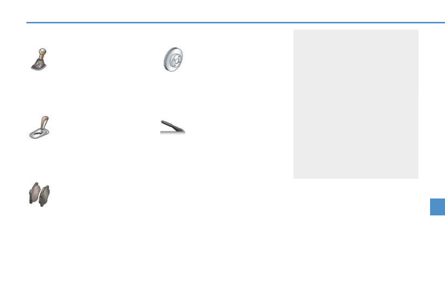
  Automatic  gearbox 


The gearbox does not re-

quire any maintenance (no oil 

change). 


Refer to the warranty and 

maintenance record for de-

tails of the checking intervals 

for this component.  

  Brake disc and drum wear 


For any information relating 

to checking of the brake disc 

and/or drum wear, contact a 

PEUGEOT dealer or a quali-

fi ed workshop.  

  Manual  gearbox 


The gearbox does not re-

quire any maintenance (no oil 

change). 


Refer to the warranty and 

maintenance record for details 

of the level checking intervals 

for this component.  

  Brake  pads 

 Brake wear depends on the 

style of driving, particularly in 

the case of vehicles used in 

town, over short distances. It 

may be necessary to have the 

condition of the brakes checked, even 

between vehicle services. 

 Unless there is a leak on the circuit, a 

drop  in  the  brake  fl uid  level  indicates 

that the brake pads are worn.  

  Parking  brake 

 If the parking brake travel is 

too long or if you notice a loss 

of effectiveness of this sys-

tem, the parking brake must 

be adjusted, even between 

two services. 


This system must be checked by a 

PEUGEOT  dealer  or  a  qualifi ed  work-

shop. 

9

i

i

128

207CC_EN_CHAP09_INFO PRATIQUES_ED01-2014

TEMPORARY PUNCTURE 

REPAIR KIT 

  Description of the kit 

  The speed limit sticker  

I  must be 

affi xed  to  the  vehicle's  steering 

wheel to remind you that a wheel is 

in temporary use. 

 Do not exceed a speed of 50 mph 

(80 km/h) when driving with a tyre 

repaired using this type of kit.   


A.   "Sealant" or "Air" position selector. 


B.   On   "I"  / off  "O"   switch. 


C.   Defl ation button. 


D.   Pressure gauge (in bar and p.s.i.). 


E.   Compartment  housing: 

   -   a cable with adaptor for 12 V socket, 
  -   various  infl ation  adaptors  for  ac-

cessories, such as balls, bicycle 

tyres...  


F.   Sealant  cartridge. 


G.   White pipe with cap for repair. 


H.   Black pipe for infl ation. 


I.   Speed  limit  sticker.  

  Complete system consisting of a com-

pressor and a sealant cartridge which 

permits  

temporary repair  of a tyre so 

that you can drive to the nearest ga-

rage. 

 It is designed to repair most punctures 

which could affect the tyre, located on 

the tyre tread or shoulder.    

  The vehicle's electric system allows 

the connection of a compressor for 

long  enough  to  infl ate  a  tyre  after 

a  puncture  repair  or  for  infl ating  a 

small infl atable accessory.  

9

i

!

!

PRACTICAL INFORMATION

129

207CC_EN_CHAP09_INFO PRATIQUES_ED01-2014

  Avoid removing any foreign bodies 

which have penetrated into the tyre.  

  Take care, this product is harmful 

(e.g. ethylene-glycol, colophony...) 

if swallowed and causes irritation 

to the eyes. 

 Keep this product out of the reach 

of  children.  

  Repair  procedure 

  1.  Sealing  

       Switch  off  the  ignition.   

       Uncoil the white pipe  

G   fully. 

     Unscrew the cap from the white pipe. 

     Connect the white pipe to the valve 

of the tyre to be repaired.   

      Connect the compressor's electric 

plug to the vehicle's 12 V socket. 

     Start the vehicle and leave the engine 

running.   

  Do not start the compressor be-

fore connecting the white pipe to 

the tyre valve: the sealant product 

would be expelled through the pipe.  

       Turn the selector  

A  to the 

"sealant" position. 

     Check that the switch  

B  is in 

position  

"O" .   

9

i

PRACTICAL INFORMATION

130

207CC_EN_CHAP09_INFO PRATIQUES_ED01-2014

  If after around 5 to 7 minutes the 

pressure is not attained, this indi-

cates that the tyre is not repairable; 

contact a PEUGEOT dealer or a 

qualifi ed workshop for assistance.    

       Switch on the compressor by mov-

ing the switch  

B  to position  "I"   until 

the tyre pressure reaches 2.0 bars.  


The sealant is injected into the tyre 

under pressure; do not disconnect 

the pipe from the valve during this 

operation (risk of splashing).   

       Remove the kit and screw the cap 

back on the white pipe.  


Take care to avoid staining your ve-

hicle with traces of fl uid. Keep the kit 

to hand. 

     Drive immediately for approximately 

three miles (fi ve kilometres), at reduced 

speed (between 15 and 35 mph (20 and 

60 km/h)), to plug the puncture. 

     Stop to check the repair and the tyre 

pressure using the kit.   

9

!

PRACTICAL INFORMATION

131

207CC_EN_CHAP09_INFO PRATIQUES_ED01-2014


As soon as possible, go to a 

PEUGEOT  dealer  or  a  qualifi ed 

workshop. 

 You must inform the technician 

that you have used this kit. Af-

ter inspection, the technician will 

advise you on whether the tyre 

can be repaired or if it must be 

replaced.  

  2. Infl ation  

       Turn the selector  

A  to the 

"air" position. 

     Uncoil the black pipe  

H   fully. 

    Connect the black pipe to 

the valve of the wheel.   

      Connect the compressor's electric 

plug to the vehicle's 12 V socket. 

     Start the vehicle again and leave the 

engine  running.   

       Adjust the pressure using the com-

pressor  (to  infl ate:  switch   

B  in po-

sition  

"I" ;  to  defl ate:  switch   B   in 

position  

"O"  and press button  C ), 

in accordance with the vehicle's tyre 

pressure label (located on the left 

hand door aperture).   


A loss of pressure indicates that the 

puncture has not been fully plugged; 

contact a PEUGEOT dealer or qual-

ifi ed workshop for assistance. 

     Remove and stow the kit. 

   

 Drive at reduced speed (50 mph 

[80 km/h] max) limiting the distance 

travelled to approximately 120 miles 

(200  km).    

9

!

PRACTICAL INFORMATION

132

207CC_EN_CHAP09_INFO PRATIQUES_ED01-2014

  Beware of discharges of fl uid. 

 The expiry date of the fl uid is indi-

cated on the cartridge. 

 The sealant cartridge is designed 

for single use; even if only partly 

used, it must be replaced. 

 After use, do not discard the car-

tridge into the environment, take 

it to an authorised waste disposal 

site or a PEUGEOT dealer. 


Do not forget to obtain a new 

sealant cartridge, available from 

 PEUGEOT dealers or from a qual-

ifi ed workshop.   

  Removing  the  cartridge 

       Stow the black pipe. 

    Detach the angled base from the 

white pipe. 

     Support the compressor vertically. 

     Unscrew the cartridge from the bottom.   

  Checking tyre pressures / 

inflating accessories 

  You can also use the compressor, with-

out injecting any product, to: 

   -   check or adjust the pressure of your 

tyres, 

  -   infl ate  other  accessories  (balls,  bi-

cycle  tyres...).   

       Turn the selector  

A  to the 

"Air" position. 

     Uncoil the black pipe  

H   fully. 

    Connect the black pipe to 

the valve of the wheel or accessory.  


If necessary, fi t one of the adaptors 

supplied with the kit fi rst.   

     

 Connect the compressor's electri-

cal connector to the vehicle's 12 V 

socket. 

     Start the vehicle and let the engine 

run. 

     Adjust the pressure using the com-

pressor  (to  infl ate:  switch   

B  in po-

sition  

"I" ;  to  defl ate:  switch   B   in 

position  

"O"  and press button  C ), 

according to the vehicle's tyre pres-

sure label or the accessory's pres-

sure label. 

     Remove the kit then stow it.    

9

i

PRACTICAL INFORMATION

133

207CC_EN_CHAP09_INFO PRATIQUES_ED01-2014

  *    According  to  country.  

CHANGING  A  WHEEL *  

 Procedure for changing a faulty wheel 

for the spare wheel using the tools pro-

vided with the vehicle. 

  Access to the tools 

 The tools are installed in a box at the 

bottom of the boot under the spare 

wheel. 

 For access to them, refer to the para-

graph "Access to the spare wheel" on 

the following page. 

  List  of  tools 


1.   Wheelbrace.  


For removal of the wheel trim and 

removal of the wheel fi xing bolts. 


2.   Jack with integral handle.  


For raising the vehicle. 


3.   "Bolt  cover"  tool.  


For removal of the bolt protectors 

(covers) on alloy wheels. 


4.   Socket for the security bolts (located 

in the glove box).  


For adaptation of the wheelbrace 

to the special "security" bolts.   


5.   Removable  towing  eye.  

  Refer to the paragraph "Towing 

the vehicle". 

 All of these tools are specifi c to your 

vehicle. Do not use them for other 

purposes.  

  Other  accessories 

  Wheel  with  trim 


When removing the wheel , 

detach  the  trim  fi rst  using  the 

wheelbrace  

1  pulling at the valve 

passage hole. 


When  refi tting  the  wheel ,  re-

fi t  the  trim  starting  by  placing  its 

notch facing the valve and press 

around its edge with the palm of 

your  hand.   

9

i

i

PRACTICAL INFORMATION

134

207CC_EN_CHAP09_INFO PRATIQUES_ED01-2014

  Access to the spare wheel 

 The "space-saver" spare wheel is in-

stalled in the boot under the fl oor. 

 To gain access to it: 

      place the vehicle in the "coupé" con-

fi guration, 

     open the boot, 

     raise the fl oor.  

  Fixing the "space-saver" spare 

wheel 

 If  your  vehicle  is  fi tted  with  alloy 

wheels, it is normal to notice, when 

tightening  the  bolts  on  fi tting,  that 

the washers do not come into con-

tact with the "space-saver" spare 

wheel. The wheel is secured by the 

conical contact of each bolt.  

  Taking out the wheel 

     Slacken and remove the retaining 

strap. 

     Raise the spare wheel towards you 

from the rear. 

     Take the wheel out of the boot.   

  Putting the wheel back in place 

      Put the spare wheel back in its housing. 

     Put the retaining strap back in place 

and tighten it. 

     Put the boot fl oor back in place.   

  Tyre under-infl ation detection 

 The spare wheel is not fi tted with a 

sensor. The punctured wheel must 

be repaired by a PEUGEOT dealer.   

9

i

PRACTICAL INFORMATION

135

207CC_EN_CHAP09_INFO PRATIQUES_ED01-2014

  Parking  the  vehicle 


Immobilise the vehicle where it 

does  not  block  traffi c:  if  possible, 

park the vehicle on level, stable 

and non-slippery ground. 

 Apply the parking brake, switch off 

the ignition and engage fi rst gear *  

to lock the wheels. 

 If necessary, place a chock under 

the wheel diagonally opposite the 

wheel to be changed. 

 It is imperative that you ensure that 

the occupants get out of the vehicle 

and wait in a safe location. 


Never go underneath a vehicle 

raised using a jack; use an axle 

stand.  

  List  of  operations 

      Remove the chromed bolt cover from 

each of the bolts using the tool  

3 . 

   

 If your vehicle is equipped with 

this, fi t the security socket  

4  on the 

wheelbrace  

1  to slacken the security 

bolt. 

    Slacken the other bolts using the 

wheelbrace  

1   only. 

     Place the jack  

2  in contact with one 

of the two front  

A  or rear  B   locations 

provided on the underframe, which-

ever is closest to the wheel to be 

changed. 

     Extend the jack  

2  until its base plate 

is in contact with the ground. Ensure 

that the centreline of the jack base 

plate is directly below the location  

A  

or  

B   used. 

     Raise the vehicle until there is suf-

fi cient space between the wheel and 

the ground to admit the spare (not 

punctured) wheel easily. 

     Remove the bolts and store them in 

a clean place. 

     Remove  the  wheel.    

  *  position  

P  for the automatic gearbox.  

9

i

PRACTICAL INFORMATION

136

207CC_EN_CHAP09_INFO PRATIQUES_ED01-2014

  After changing a wheel 

 Using the "space-saver" spare wheel: 

      do not fi t the wheel trim, 

     do not exceed a speed of 50 mph 

(80  km/h).  

 Have the tightening of the bolts and 

the pressure of the spare wheel 

checked by a PEUGEOT dealer 

without delay. 

 Have the punctured wheel repaired 

and replace it on the vehicle as 

soon as possible.  

  Fitting  a  wheel 

  List  of  operations 

      Put the wheel in place on the hub. 

     Screw in the bolts by hand. 

   

 Pre-tighten the security bolt us-

ing the wheelbrace  

1  fi tted with the 

security socket  

4  (if your vehicle is 

equipped with this). 

     Pre-tighten the other bolts using the 

wheelbrace  

1   only. 

     Lower the vehicle fully. 

     Fold the jack  

2  and detach it. 

     Tighten the security bolt using the 

wheelbrace  

1  fi tted with the security 

socket  

4  (if your vehicle is equipped 

with this). 

   

 Tighten the other bolts using the 

wheelbrace  

1   only. 

     Refi t  the  chromed  bolt  covers  on 

each of the bolts. 

     Store the tools in the box at the bottom 

of the boot. 

     Store the punctured wheel in a corner 

of  the  boot.    

9

i

i

i

PRACTICAL INFORMATION

137

207CC_EN_CHAP09_INFO PRATIQUES_ED01-2014

     SNOW  CHAINS 

  In wintry conditions, snow chains im-

prove traction as well as the behaviour 

of the vehicle when braking. 

  The  snow  chains  must  be  fi tted 

only to the front wheels. They must 

never  be  fi tted  to  "space-saver" 

type spare wheels.  

  Take account of the legislation in 

force in your country on the use 

of snow chains and the maximum 

running speed authorised.  

  Advice  on  installation 

      If  you  have  to  fi t  the  chains  during 

a journey, stop the vehicle on a fl at 

surface on the side of the road. 

     Apply the parking brake and posi-

tion any wheel chocks to prevent 

movement of your vehicle. 

     Fit the chains following the instruc-

tions provided by the manufacturer. 

     Move off gently and drive for a few 

moments, without exceeding 30 mph 

(50 km/h). 

     Stop your vehicle and check that the 

snow chains are correctly tightened.   

  Avoid driving with snow chains on 

roads that have been cleared of 

snow, to avoid damaging your ve-

hicle's tyres and the road surface. 

It is recommended that before you 

leave, you practise fi tting the snow 

chains on a level and dry surface. 

If  your  vehicle  is  fi tted  with  alloy 

wheels, check that no part of the 

chain or its fi xings is in contact with 

the  wheel  rim.   

          Use only the chains designed to be fi t-

ted  to  the  type  of  wheel  fi tted  to  your 

vehicle: 

  Original  tyre  size  

  Chain 

specifi cation  

  205/45  R17  

  Maximum  link 

size: 7 mm  

 For more information on snow chains, 

contact a PEUGEOT dealer or a quali-

fi ed workshop.   

9

i

i

PRACTICAL INFORMATION

138

207CC_EN_CHAP09_INFO PRATIQUES_ED01-2014

CHANGING A BULB 


1.    Direction indicators 

(PY21W amber).  


2.    Sidelamps (W5W).  


3.    Dipped beam headlamps 

(H7-55W).  


4.    Main beam headlamps (H1-55W).  


5.    Directional headlamps (H7-55W).  


6.    Foglamps (H11-55W).    

  Changing the direction indicator 

bulbs 


Changing a bulb should only be 

done after the headlamp has been 

switched off for several minutes 

(risk of serious burns). 

      Do not touch the bulb directly 

with your fi ngers, use a lint-free 

cloth.  

 It is imperative to use only anti-

ultraviolet (UV) type bulbs to avoid 

damaging the headlamp. 

 Always replace a failed bulb with a 

new bulb with the same type and 

specifi cation.     

                                   Model with conventional lamps 


Amber coloured bulbs, such as 

the direction indicators, must be 

replaced with bulbs of identical 

specifi cation and colour.  

      Turn the bulb holder one quarter of 

a turn and remove it. 

     Pull the bulb then change it.  

 To  refi t,  carry  out  these  operations  in 

reverse order. 

   The headlamps are fi tted with polycar-

bonate glass with a protective coating: 

       

do not clean them using a dry or 

abrasive cloth, nor with a deter-

gent or solvent product,  

     use a sponge and soapy water or a 

pH neutral product, 

     when using a high pressure washer 

on persistent marks, do not keep the 

lance directed towards the lamps or 

their edges for too long, so as not to 

damage their protective coating and 

seals.   

 Model with elliptical module dipped 

beam headlamps and directional 

headlamps 

  Front  lamps  

9

PRACTICAL INFORMATION

139

207CC_EN_CHAP09_INFO PRATIQUES_ED01-2014

  Changing the integrated direction 

indicator side repeaters 

  Changing the foglamp bulbs 

 For replacement of these bulbs, contact 

a PEUGEOT dealer.  

    

 Insert a screwdriver towards the 

centre of the repeater between the 

repeater and the base of the mirror. 

   

 Tilt the screwdriver to extract the 

repeater and remove the repeater. 

     Disconnect the repeater connector.  

 To  refi t,  carry  out  these  operations  in 

reverse order. 

 To obtain a replacement repeater, con-

tact a PEUGEOT dealer.   

  Changing the sidelamp bulbs 

    

 Disconnect the main headlamp 

connector. 

     Remove the plastic protective cover 

by pulling on the tab. 

     Turn the bulb holder one quarter of 

a turn and remove it. 

     Pull the bulb and change it.  

 To  refi t,  carry  out  these  operations  in 

reverse  order.  

  Changing the dipped, main beam or 

directional headlamp bulbs 

    

 Disconnect the main headlamp 

connector. 

   

 Remove the corresponding plastic 

protective cover by pulling on the tab. 

   

 Disconnect the connector of the 

corresponding lamp. 

     Move aside the spring to release the 

bulb and remove the bulb.  

 To  refi t,  carry  out  these  operations  in 

reverse  order.  

9

i

PRACTICAL INFORMATION

140

207CC_EN_CHAP09_INFO PRATIQUES_ED01-2014

Rear lamps 


1.    Brake lamps (P 21 W).  


2.    Sidelamps (LEDs).  


3.    Foglamps (P 21 W).  


4.    Direction indicators (PY 21 W 

a mber).  


5.    Reversing lamps (R 10 W).   

  Changing  bulbs 

 These bulbs (with the exception of the diode 

lamps) are changed from outside the boot: 

      fi rst open the fl ap to gain access to 

the fi xing bolt, 

     remove the lamp fi xing bolt, 

     remove the lamp from the outside, 

     disconnect the lamp connector, 

     remove the lamp seal, 

     press the four tabs and remove the 

bulb holder, 

     turn the bulb one quarter of a turn 

and change it.  

 To refi t, carry out these operations in re-

verse  order.  

 Amber coloured bulbs, such as the 

direction indicators, must be re-

placed with bulbs of identical speci-

fi cation and colour. 

9

!

PRACTICAL INFORMATION

141

207CC_EN_CHAP09_INFO PRATIQUES_ED01-2014

  Changing the third brake lamp 

(LEDs) 

 For the replacement of this type of LED 

lamp, contact a PEUGEOT dealer or a 

qualifi ed workshop.  

  Changing the number plate lamp 

bulbs (W 5 W) 

      Insert a thin screwdriver in one of 

the exterior holes of the lens. 

     Push it towards the outside to unclip it. 

     Remove the lens. 

     Pull the bulb and change it.   


High pressure washing  

 When using this type of washing 

on stubborn dirt, do not persist on 

the headlamps, the lamps and their 

surrounds to avoid damaging their 

protective coating and seals.  

9

!

i

PRACTICAL INFORMATION

142

207CC_EN_CHAP09_INFO PRATIQUES_ED01-2014


PEUGEOT does not accept any 

responsibility for the costs incurred 

in repairing your vehicle or for the 

malfunctions resulting from the in-

stallation of additional accessories 

which are not supplied or recom-

mended by PEUGEOT and which 

are not installed in accordance with 

its instructions, particularly when 

the combined consumption of all of 

the additional equipment connect-

ed exceeds 10 milliamperes.   


Installation of electrical acces-

sories  


Your vehicle's electrical circuit 

is designed to operate with the 

standard or optional equipment. 


Before installing other electrical 

equipment or accessories in your 

vehicle, contact a PEUGEOT dealer 

or a qualifi ed workshop. 

CHANGING A FUSE 


Procedure for the replacement of a 

failed fuse with a new fuse in order to 

rectify a failure of the corresponding 

function. 

  Access to the tools 

 The extraction tweezer is installed on the 

back of the dashbaord fusebox cover. 

 To gain access to it: 

      unclip the cover pulling at the top, 

     remove the cover completely, 

     remove  the  tweezer.   

  Replacing  a  fuse 

 Before replacing a fuse, the cause of the 

failure must be identifi ed and rectifi ed. 

      Identify the failed fuse by examining 

the condition of its fi lament.  

      Use the special tweezer to extract 

the fuse from its housing. 

     Always replace the faulty fuse with a 

fuse of the same rating. 

     Check that the number marked on 

the box and the rating marked on 

the top of the fuse correspond to the 

following  tables.  

  Good  

  Failed 


Content   ..  7  8  9  10   ..