Nissan Qashqai (2007-2010). Manual - part 970
 

  Index      Nissan     Nissan Qashqai - service and repair manual 2007 - 2010 year


Search            copyright infringement  


Content   ..  968  969  970  971   ..


Nissan Qashqai (2007-2010). Manual - part 970


INSTRUMENT PANEL ASSEMBLY

IP-13

< ON-VEHICLE REPAIR >

C

D

E

F

G

H

I

K

L

M

A

B

IP

N

O

P

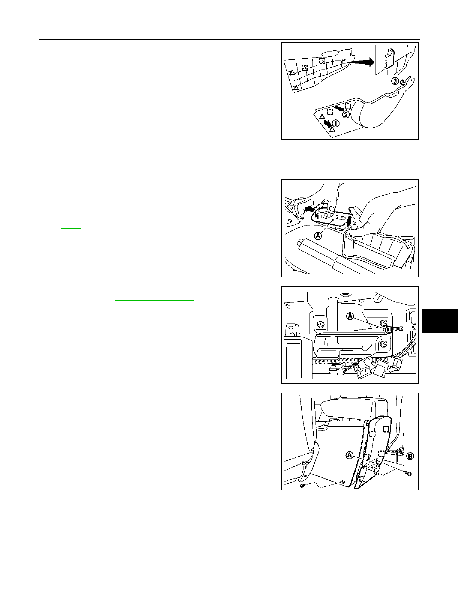
7.

Remove lower instrument panel covers. (RH / LH)
• Pull from the rear of lower instrument panel cover to release

rear pawls (1) and clips (2), use flat screwdriver or other suit-
able tool to release upper metal clip (3).

• Pull backward to release lower instrument panel cover from

instrument panel.

CAUTION:

To avoid damaging parts, it is important to take care for
removal of this part.

8.

Remove center console front fixing screws and clip.

9.

Remove cup holder.
• Pull upward to release cup holder pawls from center console.

10. Remove panel door lock and 4/2WD switch console (A) as

shown.
• Push panel switch console assembly from inner center con-

sole.

• Disconnect harness connectors. Refer to 

DLK-280, "Exploded

View"

.

11. Remove hand brake cable adjusting nut (A) to loosen cable suf-

ficiently. Refer to 

PB-5, "Exploded View"

.

12. Remove center console rear finisher.

• Pull back release metal clip from center console.
• Remove inside key antenna and connector (A).
• Disconnect harness connector fixing clip.
• Remove key antenna fixing screw (B).

13. Remove center console rear fixing screws, move forward front seats if necessary. For electrical seat refer

to 

IP-8, "Precaution"

.

14. Remove center console assembly. Refer to 

IP-18, "Exploded View"

.

CAUTION:

Always move center console with caution to avoid damaging seats, or other part. 

15. Remove display unit. Refer to 

AV-203, "Exploded View"

.

E1JIA0009ZZ

E1JIA0012ZZ

E1JIA0014ZZ

E1JIA0011ZZ

IP-14

< ON-VEHICLE REPAIR >

INSTRUMENT PANEL ASSEMBLY

16. Remove cluster lid C.

• Using flat screwdriver or other suitable tool, and shop cloth,

release front metal clip.

• Pull back cluster lid C from lower to upper part. 
• Disconnect harness connectors.
• Remove hazard switch. Refer to 

EXL-179, "Exploded View"

.

• Remove seat belt warning unit. Refer to 

SBC-36, "Removal

and Installation"

.

• Remove center air grille assembly. Refer to 

VTL-43, "CENTER

VENTILATOR GRILLES : Exploded View"

 (Automatic air con-

ditioner), 

VTL-89, "CENTER VENTILATOR GRILLES :

Exploded View"

 (Manual air conditioner).

17. Remove AC controller fixing screws (A), then release AC con-

troller from instrument panel.

18. Remove CD changer unit (if equipped).

• Remove fixing screws.
• Disconnect harness connector.

19. Disconnect inside key antenna connector and clip located under

audio unit (if equipped). 

20. Remove audio unit (if equipped). Refer to 

AV-33, "Exploded

View"

 (without navigation)

AV-202, "Exploded View"

 (with navi-

gation).

21. Remove front side of body side welt LH. Refer to 

INT-14,

"Exploded View"

.

22. Remove front pillar garnish (LH and RH). Refer to 

INT-14, "Removal and Installation"

.

23. Remove driver side instrument side finisher.

• Insert a remover tool into lower space.
• Pull the instrument side finisher crosswise.

24. Remove lower instrument panel, driver side.

• Remove hood opener (A) mounting bolts. Refer to 

DLK-227,

"HOOD LOCK CONTROL : Exploded View"

.

• Remove fuse box lid (B).
• Remove data link connector.
• Pull back lower instrument panel (1), driver side.
• Disconnect harness connectors.
• Remove AC sensor.
• Release date link connector (pawl) then remove it from lower

instrument panel, driver side.

25. Remove steering wheel. Refer to 

ST-9, "Removal and Installation"

.

E1JIA0004ZZ

E1JIA0005ZZ

E1JIA0019ZZ

E1JIA0016ZZ

INSTRUMENT PANEL ASSEMBLY

IP-15

< ON-VEHICLE REPAIR >

C

D

E

F

G

H

I

K

L

M

A

B

IP

N

O

P

26. Remove steering column covers.

• Release steering column handle.
• Remove steering column escutcheon (1).
• Remove steering column front lower cover (2) fixing screw (5),

then remove it.

• Remove steering column front lower protector (3) (if

equipped).

• Pull steering column cover upper (4).
• Release fixing clip from steering column finisher (6), then

remove steering column upper.

• Disconnect ADP steering switch connector (with automatic

drive position).

27. Remove spiral cable. Refer to 

SR-6, "Removal and Installation"

.

28. Remove combination switch. Refer to 

EXL-175, "Exploded View"

.

29. Remove paddle ESP and mirror switch LH/RH.

30. Remove cluster lid A.
31. Remove combimeter.

• Remove combimeter fixing screws.
• Pull combimeter.
• Disconnect harness connectors.

32. Remove defroster grille LH. Refer to 

VTL-46, "SIDE DEFROSTER DUCTS : Exploded View"

 (Automatic

air conditioner), 

VTL-91, "SIDE DEFROSTER DUCTS : Exploded View"

 (Manual air conditioner).

• Pull upward, disengage pawls.
• Disconnect harness connector.

33. Remove defroster grille RH. Refer to 

VTL-46, "SIDE DEFROSTER DUCTS : Exploded View"

 (Automatic

air conditioner), 

VTL-91, "SIDE DEFROSTER DUCTS : Exploded View"

 (Manual air conditioner).

• Pull upward, disengage pawls.
• Disconnect harness connector (if equipped).

34. Remove key antenna. Refer to 

DLK-273, "INSTRUMENT CENTER : Removal and Installation"

.

35. Remove front part of body side welt RH. Refer to 

INT-14, "Exploded View"

.

36. Remove front pillar garnish RH. Refer to 

INT-14, "Removal and Installation"

.

37. Remove passenger side instrument side finisher (1).

• Insert a remover tool into lower space.
• Pull the instrument side finisher crosswise.

E1JIA0018ZZ

E1JIA0015ZZ

E1JIA0006ZZ

IP-16

< ON-VEHICLE REPAIR >

INSTRUMENT PANEL ASSEMBLY

38. Remove lower instrument panel passenger side.

• Remove rear fixing clip (A).
• Pull downward to disengage pawls.
• Pull back instrument passenger lower cover (1).

39. Remove glove box assembly.

• Open the glove box.
• Remove fixing screws (A).
• Pull up glove box assembly (1).
• Remove glove box bulb assembly.
• Remove damper pin (2) of outer side.
• Remove glove box door.
• Remove latch.

40. Remove tweeter grille RH.

• Disconnect tweeter harness connector.
• Disconnect sun load sensor (if equipped).

41. Remove lower instrument panel passenger side.

• Remove lower instrument panel passenger mounting screws.
• Disconnect harness connector.
• Pull back lower instrument panel.
• Disconnect harness connector sensor.
• Remove ambient sensor.

42. Disconnect passenger airbag module connector. Refer to 

SR-8, "Removal and Installation"

.

43. Remove passenger airbag module fixing bolt. Refer to 

SR-8, "Exploded View"

.

44. Remove passenger airbag. Refer to 

SR-8, "Removal and Installation"

.

45. Disconnect antenna harness connectors (A), then remove har-

ness clips, from front pillar.
• Release lower passenger side insulator from lower instrument

panel.

• Release harness clip from instrument panel.

46. Remove instrument panel & pad.

E1JIA0020ZZ

E1JIA0007ZZ

E1JIA0021ZZ

E1JIA0022ZZ


Content   ..  968  969  970  971   ..