Nissan Qashqai (2007-2010). Manual - part 735
 

  Index      Nissan     Nissan Qashqai - service and repair manual 2007 - 2010 year


Search            copyright infringement  


Content   ..  733  734  735  736   ..


Nissan Qashqai (2007-2010). Manual - part 735


BRC-138

< COMPONENT DIAGNOSIS >

[ESP/TCS/ABS]

C1147, C1148, C1149, C1150 USV/HSV LINE

C1147, C1148, C1149, C1150 USV/HSV LINE

Description

INFOID:0000000000924882

USV1, USV2 (CUT VALVE)

The cut valve shuts off the normal brake fluid path from the master cylinder, when ESP/TCS is activated.

HSV1, HSV2 (SUCTION VALVE)

The suction valve supplies the brake fluid from the master cylinder to the pump, when ESP/TCS is activated.

DTC Logic

INFOID:0000000000924883

DTC DETECTION LOGIC

DTC CONFIRMATION PROCEDURE

1.

CHECK SELF-DIAGNOSIS RESULTS

Check the self-diagnosis results.

Is above displayed on the self-diagnosis display?

YES

>> Proceed to diagnosis procedure. Refer to 

BRC-138, "Diagnosis Procedure"

.

NO

>> INSPECTION END

Diagnosis Procedure

INFOID:0000000000924884

INSPECTION PROCEDURE

1.

CHECK CONNECTOR

1.

Turn ignition switch OFF.

2.

Disconnect ABS actuator and electric unit (control unit) connector.

3.

Check terminal for deformation, disconnection, looseness, and so on. If any malfunction is found, repair or
replace terminal.

4.

Reconnect connector and then perform the self-diagnosis. Refer to 

BRC-96, "CONSULT-III Function

(ABS)"

.

Is any item indicated on the self-diagnosis display?

YES

>> GO TO 2.

NO

>> Poor connection of connector terminal. Replace or repair connector.

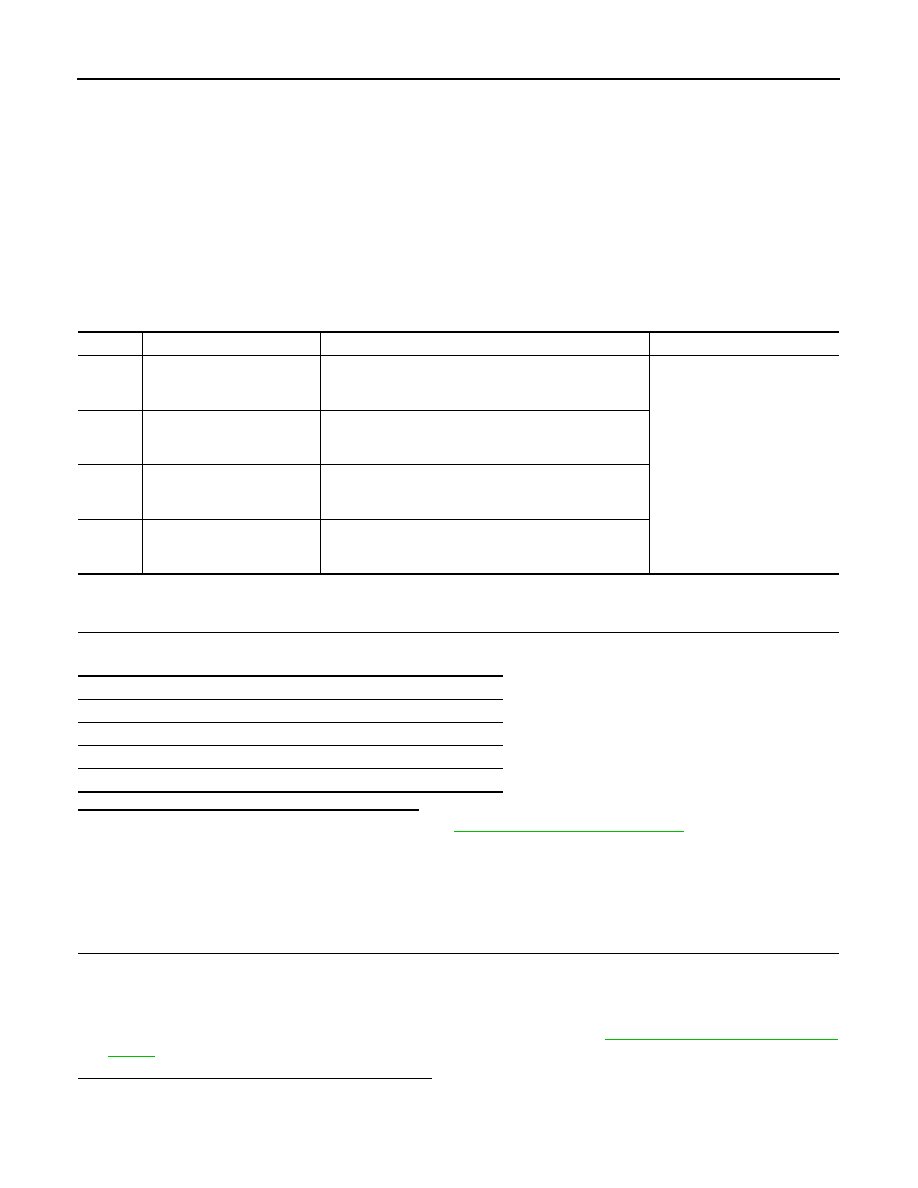
DTC

Display item

Malfunction detected condition

Possible cause

C1147

USV LINE [FL-RR]

ESP switch-over solenoid valve (USV1) on the primary 
side is open circuit or shorted, or the control line is open 
or shorted to the power supply or the ground.

• Harness or connector
• ABS actuator and electric unit 

(control unit)

C1148

USV LINE [FR-RL]

ESP switch-over solenoid valve (USV2) on the primary 
side is open circuit or shorted, or the control line is open 
or shorted to the power supply or the ground.

C1149

HSV LINE [FL-RR]

ESP switch-over solenoid valve (HSV1) on the primary 
side is open circuit or shorted, or the control line is open 
or shorted to the power supply or the ground.

C1150

HSV LINE [FR-RL]

ESP switch-over solenoid valve (HSV2) on the primary 
side is open circuit or shorted, or the control line is open 
or shorted to the power supply or the ground.

Self-diagnosis results

USV LINE [FL-RR]

USV LINE [FR-RL]

HSV LINE [FL-RR]

HSV LINE [FR-RL]

C1147, C1148, C1149, C1150 USV/HSV LINE

BRC-139

< COMPONENT DIAGNOSIS >

[ESP/TCS/ABS]

C

D

E

G

H

I

J

K

L

M

A

B

BRC

N

O

P

2.

CHECK SOLENOID, ESP SWITCH-OVER VALVE AND ACTUATOR RELAY POWER SUPPLY CIRCUIT

1.

Turn ignition switch OFF.

2.

Disconnect ABS actuator and electric unit (control unit) connector.

3.

Check voltage between ABS actuator and electric unit (control unit) harness connector terminal and
ground.

Is the inspection result normal?

YES

>> GO TO 3.

NO

>> Repair or replace malfunctioning components.

3.

CHECK SOLENOID, ESP SWITCH-OVER VALVE AND ACUATOR RELAY GROUND CIRCUIT

Check continuity between ABS actuator and electric unit (control unit) harness connector terminals and
ground.

Is the inspection result normal?

YES

>> Replace ABS actuator and electric unit (control unit).

NO

>> Repair or replace malfunctioning components.

Component Inspection

INFOID:0000000000924885

1.

CHECK ACTIVE TEST

1.

Select each test menu item on ”ACTIVE TEST“.

2.

On the display, touch “UP”, “ACT UP”, and “ACT KEEP”, and check that the system operates as shown in
the table below.

*: ON for 1 to 2 seconds after the touch, and then OFF.

ABS actuator and electric unit (control unit)

Voltage

Connector

Terminal

E36

3

Ground

Battery voltage

ABS actuator and electric unit (control unit)

Continuity

Connector

Terminal

E36

1, 4

Ground

Existed

Test item

Display item

(Note)

Display

UP

ACT UP

ACT KEEP

FR RH SOL

FR RH IN SOL

OFF

OFF

OFF

FR RH OUT SOL

OFF

OFF

OFF

USV [FR-RL]

OFF

ON

ON

HSV [FR-RL]

OFF

ON*

OFF

FR LH SOL

FR LH IN SOL

OFF

OFF

OFF

FR LH OUT SOL

OFF

OFF

OFF

USV [FL-RR]

OFF

ON

ON

HSV [FL-RR]

OFF

ON*

OFF

RR RH SOL

RR RH IN SOL

OFF

OFF

OFF

RR RH OUT SOL

OFF

OFF

OFF

USV [FL-RR]

OFF

ON

ON

HSV [FL-RR]

OFF

ON*

OFF

RR LH SOL

RR LH IN SOL

OFF

OFF

OFF

RR LH OUT SOL

OFF

OFF

OFF

USV [FR-RL]

OFF

ON

ON

HSV [FR-RL]

OFF

ON*

OFF

BRC-140

< COMPONENT DIAGNOSIS >

[ESP/TCS/ABS]

C1147, C1148, C1149, C1150 USV/HSV LINE

NOTE:

A brief moment of ON/OFF condition occurs every 20 seconds after ignition switch turned ON. This is not malfunction because it is
an operation for checking.

Is the inspection result normal?

YES

>> INSPECTION END

NO

>> Go to diagnosis procedure. Refer to 

BRC-138, "Diagnosis Procedure"

.

Special Repair Requirement

INFOID:0000000000924886

1.

ADJUSTMENT OF STEERING ANGLE SENSOR NEUTRAL POSITION

Always perform the neutral position adjustment for the steering angle sensor, when replacing the ABS actua-
tor and electric unit (control unit). Refer to 

BRC-78, "ADJUSTMENT OF STEERING ANGLE SENSOR NEU-

TRAL POSITION : Description"

.

>> END

C1155 BRAKE FLUID LEVEL SWITCH

BRC-141

< COMPONENT DIAGNOSIS >

[ESP/TCS/ABS]

C

D

E

G

H

I

J

K

L

M

A

B

BRC

N

O

P

C1155 BRAKE FLUID LEVEL SWITCH

Description

INFOID:0000000000924887

Brake fluid level switch contacts close when brake fluid level is low. This is detected by the combination meter
which sends the status of fluid level to the ABS actuator and electric unit (control unit) via the CAN communi-
cation.

DTC Logic

INFOID:0000000000924888

DTC DETECTION LOGIC

DTC CONFIRMATION PROCEDURE

1.

CHECK SELF-DIAGNOSIS RESULTS

Check the self-diagnosis results.

Is above displayed on the self-diagnosis display?

YES

>> Proceed to diagnosis procedure. Refer to 

BRC-141, "Diagnosis Procedure"

.

NO

>> INSPECTION END

Diagnosis Procedure

INFOID:0000000000924889

INSPECTION PROCEDURE

1.

CHECK BRAKE FLUID LEVEL

Check the brake fluid level.

Is the inspection result normal?

YES

>> GO TO 2.

NO

>> Investigate and fix.

2.

CHECK BRAKE WARNING LAMP 1

Check that the brake warning lamp illuminates after the ignition switch is turned ON.

Is the inspection result normal?

YES

>> GO TO 3.

NO

>> Check wiring to brake fluid level switch and combination meter.

3.

CHECK BRAKE WARNING LAMP 2

Check that the brake warning lamp in the combination meter turns ON/OFF correctly when operating the park-
ing brake.

Is the inspection result normal?

YES

>> GO TO 4.

NO

>> Check parking brake switch. Refer to 

BRC-145, "Diagnosis Procedure"

.

4.

CHECK CONNECTOR

1.

Turn ignition switch OFF.

2.

Disconnect brake fluid level switch connector and combination meter connector.

3.

Check terminal for deformation, disconnection, looseness, and so on. If any malfunction is found, repair or
replace terminal.

DTC

Display item

Malfunction detected condition

Possible cause

C1155

BR FLUID LEVEL LOW

Ignition switch ON and brake fluid signal low or not avail-
able for 10 seconds.

• Brake fluid level is low
• Brake fluid level switch
• Harness or connector
• CAN communication line
• Combination meter

Self-diagnosis results

BR FLUID LEVEL LOW


Content   ..  733  734  735  736   ..