Nissan Qashqai (2007-2010). Manual - part 718
 

  Index      Nissan     Nissan Qashqai - service and repair manual 2007 - 2010 year


Search            copyright infringement  


Content   ..  716  717  718  719   ..


Nissan Qashqai (2007-2010). Manual - part 718


BRC-70

< ON-VEHICLE REPAIR >

[ABS]

ABS ACTUATOR AND ELECTRIC UNIT (CONTROL UNIT)

ABS ACTUATOR AND ELECTRIC UNIT (CONTROL UNIT)

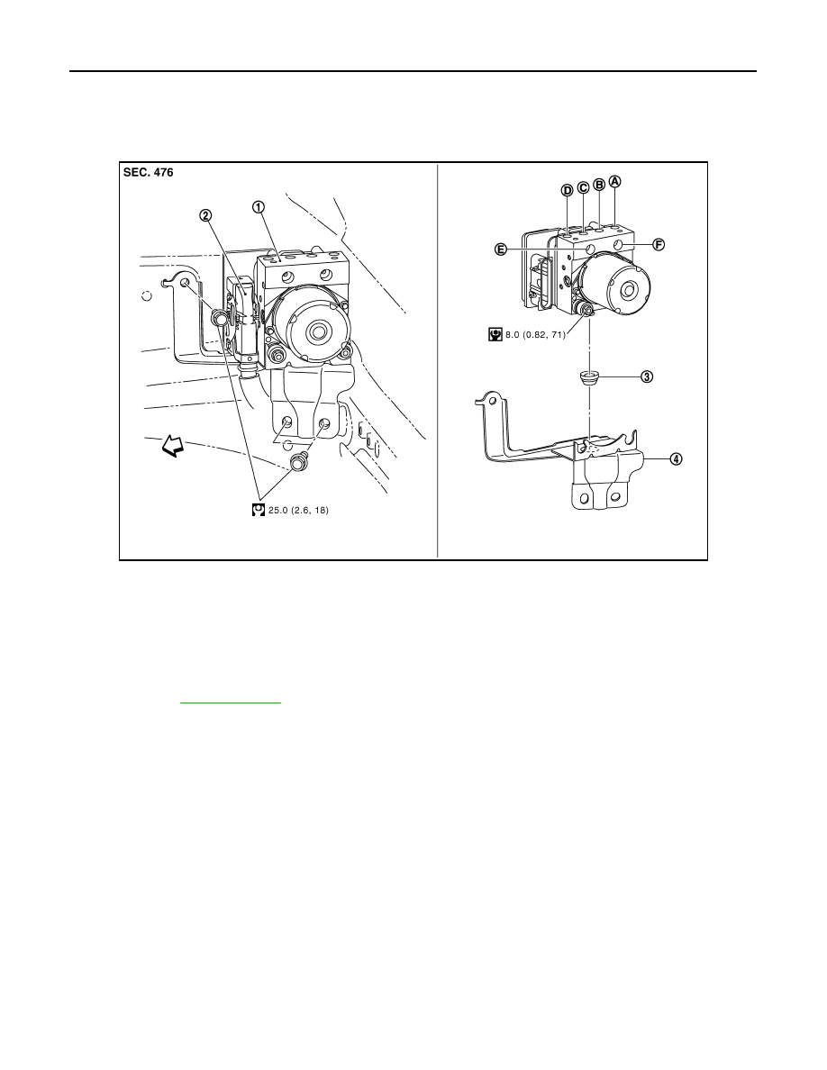
Exploded View

INFOID:0000000000925095

LHD models

JSFIA0035GB

1.

ABS actuator and electric unit (control 
unit)

2.

Connector

3.

Bushing

4.

Bracket

A.

To front LH brake caliper

B.

To rear RH brake caliper

C.

To Rear LH brake caliper

D.

To front RH brake caliper

E.

From master cylinder secondary side F.

From master cylinder primary side

: Vehicle front

Refer to GI section 

GI-4, "Components"

 for symbols in the figure.

ABS ACTUATOR AND ELECTRIC UNIT (CONTROL UNIT)

BRC-71

< ON-VEHICLE REPAIR >

[ABS]

C

D

E

G

H

I

J

K

L

M

A

B

BRC

N

O

P

RHD models

Removal and Installation

INFOID:0000000000925096

LHD MODELS

Removal

CAUTION:

• Before servicing, disconnect the battery cable from negative terminal.
• To remove brake tube, use a flare nut wrench to prevent flare nuts and brake tube from being dam-

aged. To install, use flare nut crowfoot and torque wrench.

• Do not apply excessive impact to ABS actuator and electric unit (control unit), such as dropping it.
• Do not remove and install actuator by holding harness.
• After work is completed, bleed air from brake tube. Refer to 

BR-12, "Bleeding Brake System"

 (LHD

models), 

BR-56, "Bleeding Brake System"

 (RHD models).

1.

Remove cowl top cover. Refer to 

EXT-19, "Exploded View"

.

2.

Remove exhaust manifold.
• HR16DE: 

EX-5, "Exploded View"

• MR20DE: 

EX-10, "Exploded View"

• K9K: 

EX-15, "Exploded View"

3.

Disconnect ABS actuator and electric unit (control unit) connector.

4.

Loosen brake tube flare nuts, then remove brake tubes from ABS actuator and electric unit (control unit).

5.

Remove ABS actuator and electric unit (control unit) bracket mounting nut.

6.

Remove ABS actuator and electric unit (control unit) from vehicle.

JSFIA0036GB

1.

ABS actuator and electric unit (control 
unit)

2.

Connector

3.

Bushing

4.

Bracket

A.

To front LH brake caliper

B.

To rear RH brake caliper

C.

To Rear LH brake caliper

D.

To front RH brake caliper

E.

From master cylinder secondary side F.

From master cylinder primary side

: Vehicle front

Refer to GI sectio

GI-4, "Components"

 for symbols in the figure.

BRC-72

< ON-VEHICLE REPAIR >

[ABS]

ABS ACTUATOR AND ELECTRIC UNIT (CONTROL UNIT)

Installation

Note the following, and install in the reverse order of removal.

CAUTION:

• Before servicing, disconnect the battery cable from negative terminal.
• To remove brake tube, use a flare nut wrench to prevent flare nuts and brake tube from being dam-

aged. To install, use flare nut crowfoot and torque wrench.

• Do not apply excessive impact to ABS actuator and electric unit (control unit), such as dropping it.
• Do not remove and install actuator by holding harness.
• After work is completed, bleed air from brake tube. Refer to 

BR-12, "Bleeding Brake System"

 (LHD

models), 

BR-56, "Bleeding Brake System"

 (RHD models).

• After installing harness connector in the ABS actuator and electric unit (control unit), make sure

connector is securely locked. 

RHD MODELS

Removal

CAUTION:

• Before servicing, disconnect the battery cable from negative terminal.
• To remove brake tube, use a flare nut wrench to prevent flare nuts and brake tube from being dam-

aged. To install, use flare nut crowfoot and torque wrench.

• Do not apply excessive impact to ABS actuator and electric unit (control unit), such as dropping it.
• Do not remove and install actuator by holding harness.
• After work is completed, bleed air from brake tube. Refer to 

BR-12, "Bleeding Brake System"

 (LHD

models), 

BR-56, "Bleeding Brake System"

 (RHD models).

1.

Remove cowl top cover. Refer to 

EXT-19, "Exploded View"

.

2.

Remove air cleaner and air duct.
• HR16DE: 

EM-27, "Exploded View"

• MR20DE: 

EM-144, "Exploded View"

• K9K: 

EM-265, "Exploded View"

3.

Disconnect ABS actuator and electric unit (control unit) connector.

4.

Loosen brake tube flare nuts, then remove brake tubes from ABS actuator and electric unit (control unit).

5.

Remove ABS actuator and electric unit (control unit) bracket mounting nut.

6.

Remove ABS actuator and electric unit (control unit) from vehicle.

Installation

Note the following, and install in the reverse order of removal.

CAUTION:

• Before servicing, disconnect the battery cable from negative terminal.
• To remove brake tube, use a flare nut wrench to prevent flare nuts and brake tube from being dam-

aged. To install, use flare nut crowfoot and torque wrench.

• Do not apply excessive impact to ABS actuator and electric unit (control unit), such as dropping it.
• Do not remove and install actuator by holding harness.
• After work is completed, bleed air from brake tube. Refer to 

BR-12, "Bleeding Brake System"

 (LHD

models), 

BR-56, "Bleeding Brake System"

 (RHD models).

• After installing harness connector in the ABS actuator and electric unit (control unit), make sure

connector is securely locked. 

G SENSOR

BRC-73

< ON-VEHICLE REPAIR >

[ABS]

C

D

E

G

H

I

J

K

L

M

A

B

BRC

N

O

P

G SENSOR

Exploded View

INFOID:0000000000925097

Removal and Installation

INFOID:0000000000925098

REMOVAL

CAUTION:

• Do not drop or strike G sensor, because it has little endurance to impact.
• Do not use power tool etc., because G sensor is sensitive for the impact.

1.

Remove lower instrument cover RH. Refer to 

IP-11, "Exploded View"

.

2.

Disconnect G sensor harness connector.

3.

Remove mounting nuts. Remove G sensor.

INSTALLATION

Note the following, and install in the reverse order of removal.

CAUTION:

• Do not drop or strike G sensor, because it has little endurance to impact.
• Do not use power tool etc., because G sensor is sensitive for the impact.

1.

G sensor

: Vehicle front

Refer to GI section 

GI-4, "Components"

 for symbols in the figure.

JSFIA0038GB


Content   ..  716  717  718  719   ..