Nissan Qashqai (2007-2010). Manual - part 709
BRC-34
< COMPONENT DIAGNOSIS >
[ABS]
C1114 ACTUATOR RELAY SYSTEM
YES
>> GO TO 3.
NO
>> Repair or replace malfunctioning components.
3.
ABS POWER SUPPLY CHECK (UNDER LOAD CONDITIONS)
Use 12V lamp (normal rating 10 to 20W) connected between E34 terminals 1 and 3. With ignition switch ON
check bulb illuminates correctly.
Is the inspection result normal?
YES
>> GO TO 4.
NO
>> Check both power supply and ground circuit.
4.
CHECK ABS ACTUATOR AND ELECTRIC UNIT (CONTROL UNIT) GROUND CIRCUIT
1.
Turn ignition switch OFF.
2.
Disconnect ABS actuator and electric unit (control unit) connector.
3.
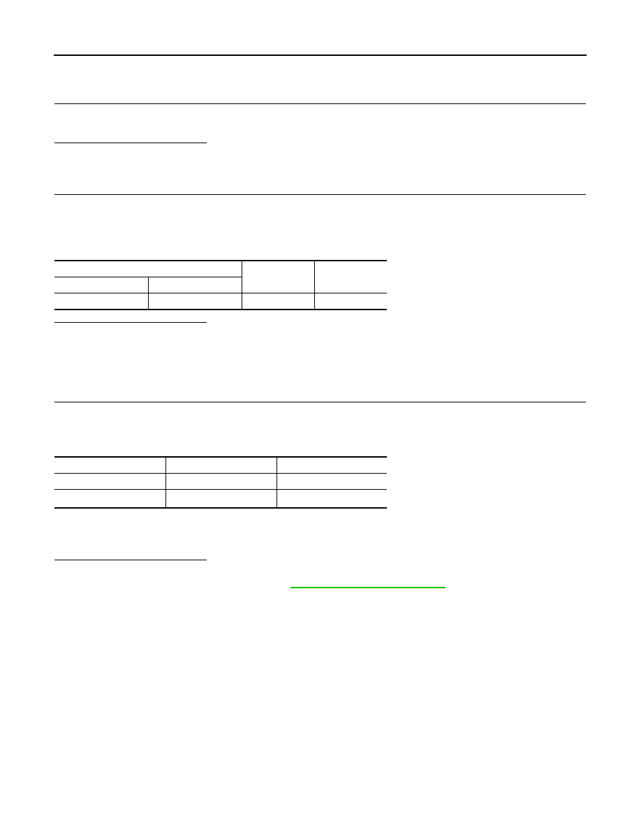
Check continuity between ABS actuator and electric unit (control unit) harness connector terminals and
ground.
Is the inspection result normal?
YES
>> Replace ABS actuator and electric unit (control unit).
NO
>> Repair or replace malfunctioning components. (Check ABS each bolt for tightness and corrosion).
Component Inspection
INFOID:0000000000924993
1.
CHECK ACTIVE TEST
1.
On “ACTIVE TEST”, select “ABS MOTOR”.
2.
Touch “ON” and “OFF” on screen. Make sure motor relay and actuator relay operates as shown in table
below.
NOTE:
A brief moment of ON/OFF condition occurs every 20 seconds after ignition switch turned ON. This is not malfunction because it is
an operation for checking.
Is the inspection result normal?
YES
>> INSPECTION END
NO
>> Go to diagnosis procedure. Refer to
ABS actuator and electric unit (control unit)
—
Continuity
Connector
Terminal
E34
1, 4
Ground
Existed
Operation
ON
OFF
MOTOR RELAY
ON
OFF
ACTUATOR RLY
NOTE
ON
ON