Nissan Qashqai (2007-2010). Manual - part 646
 

  Index      Nissan     Nissan Qashqai - service and repair manual 2007 - 2010 year


Search            copyright infringement  


Content   ..  644  645  646  647   ..


Nissan Qashqai (2007-2010). Manual - part 646


FAX-6

< PREPARATION >

[2WD]

PREPARATION

PREPARATION

PREPARATION

Special Service Tool

INFOID:0000000000970476

Tool number 
Tool name

Description

KV40107300
Boot band crimping tool

Installing boot band

KV40107500
Drive shaft attachment

Removing drive shaft

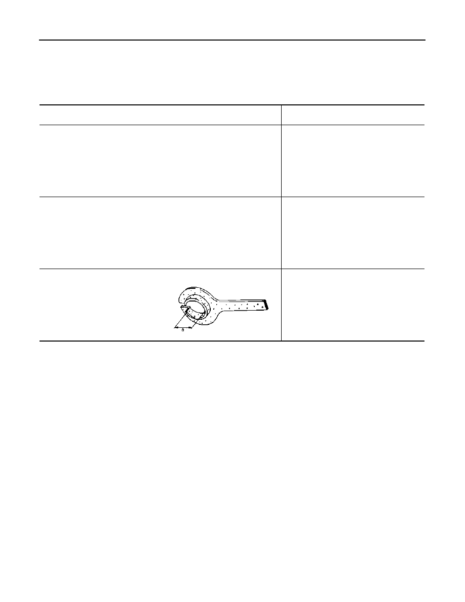
KV38107900
Protector
a: 32 mm (1.26 in) dia.

Installing drive shaft

ZZA1229D

ZZA1230D

PDIA1183J

FRONT WHEEL HUB AND KNUCKLE

FAX-7

< ON-VEHICLE MAINTENANCE >

[2WD]

C

E

F

G

H

I

J

K

L

M

A

B

FAX

N

O

P

ON-VEHICLE MAINTENANCE

FRONT WHEEL HUB AND KNUCKLE

Exploded View

INFOID:0000000000970478

Refer to 

FAX-9, "Exploded View"

.

Inspection

INFOID:0000000000970479

MOUNTING INSPECTION

Make sure that the mounting conditions (looseness, backlash) of each component and component conditions
(wear, damage) are normal.

WHEEL BEARING INSPECTION

• Move wheel hub and bearing assembly in the axial direction by hand. Make sure there is no looseness of

wheel bearing.

• Rotate wheel hub and make sure there is no unusual noise or other irregular conditions. If there is any of

irregular conditions, replace wheel hub and bearing assembly.

Standard

Axial end play

: Refer to 

FAX-40, "Wheel Bearing"

.

FAX-8

< ON-VEHICLE MAINTENANCE >

[2WD]

FRONT DRIVE SHAFT

FRONT DRIVE SHAFT

Inspection

INFOID:0000000000970480

• Check drive shaft mounting point and joint for looseness and other damage.
• Check boot for cracks and other damage.

CAUTION:

Replace entire drive shaft assembly when noise or vibration occur from drive shaft.

FRONT WHEEL HUB AND KNUCKLE

FAX-9

< ON-VEHICLE REPAIR >

[2WD]

C

E

F

G

H

I

J

K

L

M

A

B

FAX

N

O

P

ON-VEHICLE REPAIR

FRONT WHEEL HUB AND KNUCKLE

Exploded View

INFOID:0000000000970481

Removal and Installation

INFOID:0000000000970482

REMOVAL

Wheel Hub and Bearing Assembly

1.

Remove tires from vehicle.

2.

Remove wheel sensor from steering knuckle. Refer to 

BRC-67, "FRONT WHEEL SENSOR : Exploded

View"

 (with ABS), 

BRC-172, "FRONT WHEEL SENSOR : Exploded View"

 (with ESP).

CAUTION:

Never pull on wheel sensor harness.

3.

Remove lock plate from strut assembly. Refer to 

BR-19, "FRONT BRAKE (WITH ABS) : Exploded View"

(LHD with ABS), 

BR-21, "FRONT BRAKE (WITH ESP) : Exploded View"

 (LHD with ESP), 

BR-63,

"FRONT BRAKE (WITH ABS) : Exploded View"

 (RHD with ABS), 

BR-65, "FRONT BRAKE (WITH ESP) :

Exploded View"

 (RHD with ESP).

4.

Remove torque member mounting bolts. Hang torque member not to interfere with work. Refer to 

BR-37,

"BRAKE CALIPER ASSEMBLY : Exploded View"

 (LHD), 

BR-81, "BRAKE CALIPER ASSEMBLY :

Exploded View"

 (RHD).

CAUTION:

Never depress brake pedal while brake caliper is removed.

5.

Remove disc rotor.

6.

Remove cotter pin, and then loosen hub lock nut.

1.

Steering knuckle

2.

Splash guard

3.

Wheel hub and bearing assembly

4.

Cotter pin

Refer to 

GI-4, "Components"

 for symbols in the figure.

JPDIF0036GB


Content   ..  644  645  646  647   ..