Nissan Qashqai (2007-2010). Manual - part 644
 

  Index      Nissan     Nissan Qashqai - service and repair manual 2007 - 2010 year


Search            copyright infringement  


Content   ..  642  643  644  645   ..


Nissan Qashqai (2007-2010). Manual - part 644


DRIVE PINION

DLN-149

< DISASSEMBLY AND ASSEMBLY >

[REAR FINAL DRIVE: R145]

C

E

F

G

H

I

J

K

L

M

A

B

DLN

N

O

P

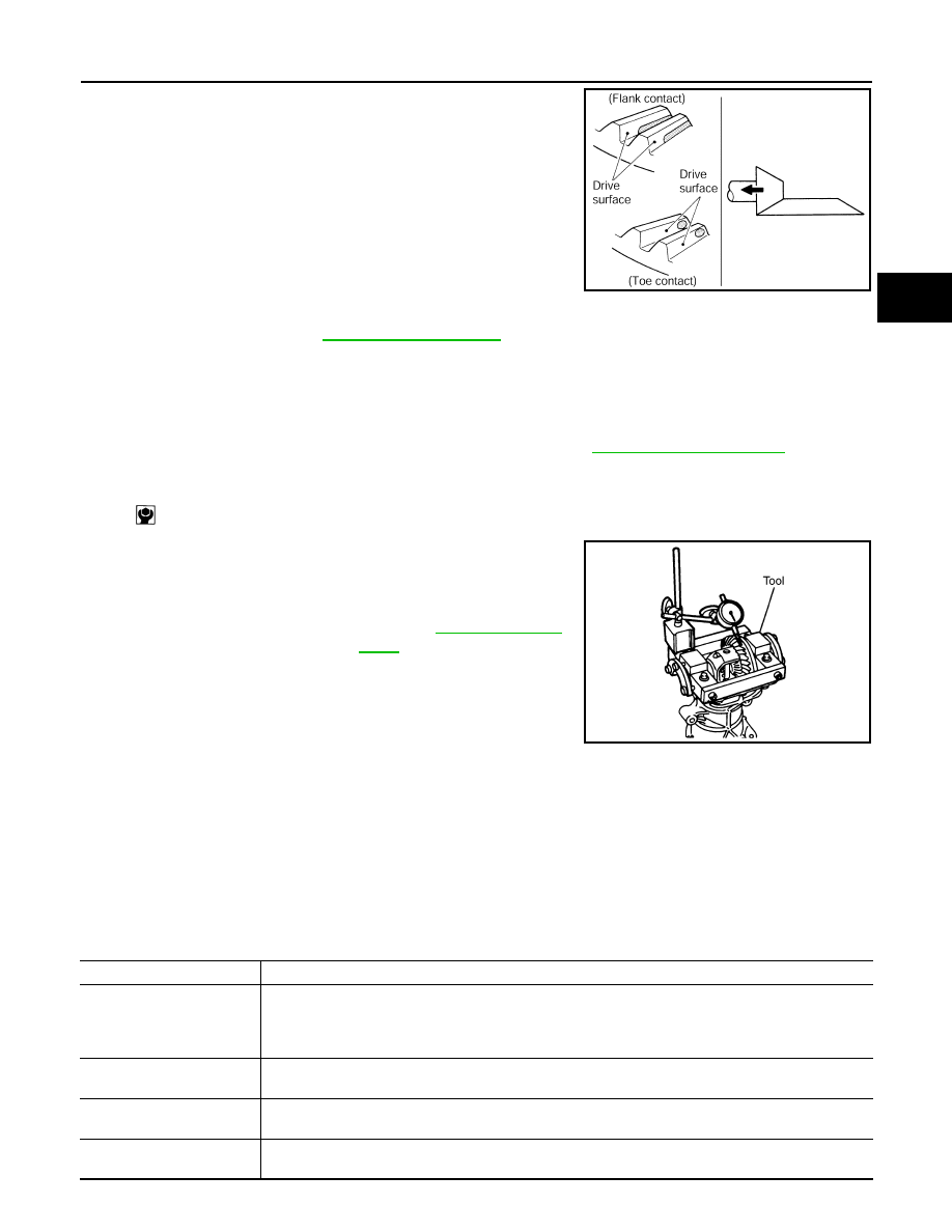
• If the tooth contact is near the flank (flank contact), or near the

toe (toe contact), thin drive pinion gear adjusting shim to move
drive pinion farther from drive gear.

BACKLASH

1.

Remove rear cover. Refer to 

DLN-135, "Disassembly"

.

2.

Following the procedure below, install a dummy cover set (SST: KV389L0010) to gear carrier.

a.

Set dummy cover shims to the right and left side bearing adjusting shims.

b.

Temporarily tighten dummy cover to gear carrier.

c.

Position dummy cover spacers to dummy cover.

d.

Tighten rear cover mounting bolts to the specified torque. Refer to 

DLN-141, "Exploded View"

.

e.

Tighten dummy cover spacer mounting bolts evenly to the specified torque.

3.

Fit a dial indicator to the drive gear face to measure the back-
lash.

• If the backlash is outside of the specified value, change the

thickness of side bearing adjusting shims.

Inspection After Disassembly

INFOID:0000000001078624

Clean up the disassembled parts. Then, inspect if the parts are worn or damaged. If so, follow the measures
below.

PDIA0441E

: 5.9 N·m (0.6 kg-m, 52 in-lb)

Standard

Backlash

: Refer to 

DLN-151, "Back-

lash"

.

When the backlash is large:

Make drive gear back adjusting shims thicker, and drive 
gear front adjusting shims thinner.

When the backlash is small:

Make drive gear back adjusting shims thinner, and 
drive gear front adjusting shims thicker.

PDIA0049E

Content

Conditions and Measures

Hypoid gear

• If the gear teeth do not mesh or line-up correctly, determine the cause and adjust or replace as nec-

essary.

• If the gears are worn, cracked, damaged, pitted or chipped (by friction) noticeably, replace with new 

drive gear and drive pinion as a set.

Bearing

If any chipped (by friction), pitted, worn, rusted or scratched mark, or unusual noise from the bearing is 
observed, replace as a bearing assembly (as a new set).

Side gear and Pinion mate 
gear

• If any cracks or damage on the surface of the tooth is found, replace.
• If any worn or chipped mark on the contact sides of the thrust washer is found, replace.

Side gear thrust washer and 
pinion mate thrust washer

If it is chipped (by friction), damaged, or unusually worn, replace.

DLN-150

< DISASSEMBLY AND ASSEMBLY >

[REAR FINAL DRIVE: R145]

DRIVE PINION

Differential case

If any wear or crack on the contact sides of the differential case is found, replace.

Companion flange

If any chipped mark (about 0.1 mm, 0.004 in) or other damage on the contact sides of the lips of the com-
panion flange is found, replace.

Content

Conditions and Measures

SERVICE DATA AND SPECIFICATIONS (SDS)

DLN-151

< SERVICE DATA AND SPECIFICATIONS (SDS) 

[REAR FINAL DRIVE: R145]

C

E

F

G

H

I

J

K

L

M

A

B

DLN

N

O

P

SERVICE DATA AND SPECIFICATIONS (SDS)

SERVICE DATA AND SPECIFICATIONS (SDS)

General Specification

INFOID:0000000000972199

Drive Gear Runout

INFOID:0000000000972200

Unit: mm (in)

Differential Side Gear Clearance

INFOID:0000000000972201

Unit: mm (in)

Preload Torque

INFOID:0000000000972202

Unit: N·m (kg-m, in-lb)

Backlash

INFOID:0000000000972203

Unit: mm (in)

Companion Flange Runout

INFOID:0000000000972204

Unit: mm (in)

Applied model

4WD

MR20DE

M/T

CVT

Final drive model

R145

Gear ratio

2.466

Number of teeth (Drive gear/Drive pinion)

37/15

Oil capacity (Approx.)

 (lmp pt)

0.55 (1)

Number of pinion gears

2

Drive pinion adjustment spacer type

Collapsible

Item

Limit

Drive gear back face runout

0.05 (0.0020)

Item

Standard

Side gear backlash (Clearance between side gear and differential 
case)

0.2 (0.008) or less

(Each gear should rotate smoothly without excessive resistance 

during differential motion.)

Item

Standard

Pinion bearing (P

1

)

0.69 – 1.18 (0.07 – 0.12, 7 – 10)

Side bearing (P

2

)

0.64 – 0.98 (0.07 – 0.09, 6 – 8)

Side bearing to pinion bearing (Total preload)
(Total preload = P

1

 + P

2

)

1.33 – 2.16 (0.14 – 0.22, 12 – 19)

Item

Standard

Drive gear to drive pinion gear

0.10 – 0.15 (0.0039 – 0.0059)

Item

Limit

Companion flange face

0.13 (0.0051)

Inner side of the companion flange

0.19 (0.0075)

FAX-1

TRANSMISSION & DRIVELINE

C

E

F

G

H

I

J

K

L

M

SECTION 

FAX

A

B

FAX

N

O

P

CONTENTS

FRONT AXLE

2WD

SYMPTOM DIAGNOSIS  ...............................

3

NOISE, VIBRATION AND HARSHNESS 
(NVH) TROUBLESHOOTING  .............................

3

NVH Troubleshooting Chart  ......................................

3

PRECAUTION ...............................................

4

PRECAUTIONS ...................................................

4

Precaution for Supplemental Restraint System 
(SRS) "AIR BAG" and "SEAT BELT PRE-TEN-
SIONER" .................................................................
..

4

Precaution Necessary for Steering Wheel Rota-
tion After Battery Disconnect ...................................
..

4

Precautions for Drive Shaft  .......................................

4

PREPARATION ............................................

6

PREPARATION ...................................................

6

Special Service Tool  .................................................

6

ON-VEHICLE MAINTENANCE .....................

7

FRONT WHEEL HUB AND KNUCKLE  ..............

7

Exploded View  ..........................................................

7

Inspection ..................................................................

7

FRONT DRIVE SHAFT ........................................

8

Inspection ..................................................................

8

ON-VEHICLE REPAIR ..................................

9

FRONT WHEEL HUB AND KNUCKLE  ..............

9

Exploded View  ..........................................................

9

Removal and Installation ...........................................

9

Inspection ................................................................

10

FRONT DRIVE SHAFT BOOT  ...........................

11

Exploded View  ........................................................

11

Replacement ...........................................................

11

FRONT DRIVE SHAFT  .....................................

15

HR16DE MODELS  .....................................................

15

HR16DE MODELS : Exploded View  .......................

15

HR16DE MODELS : Removal and Installation ........

17

HR16DE MODELS : Disassembly and Assembly ....

18

HR16DE MODELS : Inspection ...............................

22

MR20DE MODELS .....................................................

22

MR20DE MODELS : Exploded View  .......................

22

MR20DE MODELS : Removal and Installation  .......

25

MR20DE MODELS : Disassembly and Assembly 

....

26

MR20DE MODELS : Inspection  ..............................

30

K9K MODELS  ............................................................

31

K9K MODELS : Exploded View ...............................

31

K9K MODELS : Removal and Installation  ...............

33

K9K MODELS : Disassembly and Assembly ...........

34

K9K MODELS : Inspection  ......................................

38

SERVICE DATA AND SPECIFICATIONS 
(SDS) ............................................................

40

SERVICE DATA AND SPECIFICATIONS 
(SDS) .................................................................

40

Wheel Bearing  .........................................................

40

Drive Shaft ...............................................................

40

4WD

SYMPTOM DIAGNOSIS  ..............................

43

NOISE, VIBRATION AND HARSHNESS 
(NVH) TROUBLESHOOTING  ...........................

43

NVH Troubleshooting Chart  ....................................

43

PRECAUTION ..............................................

44

PRECAUTIONS .................................................

44

Precaution for Supplemental Restraint System 
(SRS) "AIR BAG" and "SEAT BELT PRE-TEN-
SIONER" .................................................................

44


Content   ..  642  643  644  645   ..