Nissan Qashqai (2007-2010). Manual - part 631
DRIVE PINION
DLN-97
< DISASSEMBLY AND ASSEMBLY >
[TRANSFER: TY30A]
C
E
F
G
H
I
J
K
L
M
A
B
DLN
N
O
P
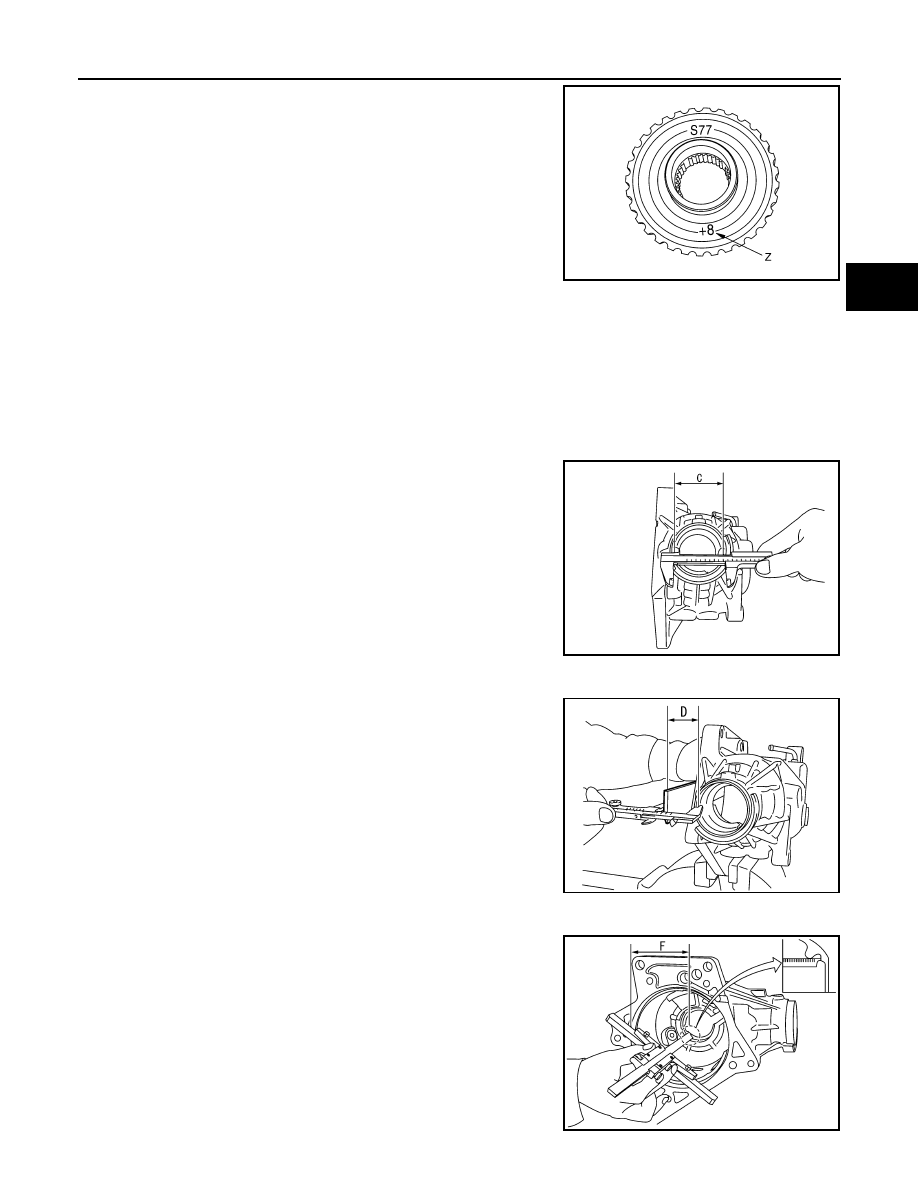
4.
Check dimension “Z” (machining difference) on the ring gear
back surface.
NOTE:
Dimension “Z” indicates difference between optimum engage-
ment and the standard dimensions in increments of 0.01 mm
(0.0004 in) written on the ring gear back surface.
5.
Calculate the thickness of the ring gear adjusting shim (adapter
case side) “T
1
” by the formula below.
6.
Select ring gear adjusting shim (adapter case side).
CAUTION:
• Only one adjusting shim can be selected.
• Select the closest one, favoring thicker over thinner when necessary if no adjusting shim with
the calculated value is available.
Ring Gear Adjusting Shim (Transfer Case Side)
1.
Measure the dimensions of each measuring point with the following procedure:
Dimension “C” measurement
• Measure the diameter of drive pinion bearing (rear side)
mounting area of transfer case with a pair of vernier calipers.
Refer to “Measuring point”.
CAUTION:
Never damage transfer case.
Dimension “D” measurement
• Measure dimension from adapter case mounting surface of
transfer case to drive pinion bearing (rear side) mounting sur-
face with a pair of vernier calipers and straightedge. Refer to
“Measuring point”.
CAUTION:
• Never damage transfer case.
• Consider the thickness of a straightedge.
Dimension “F” measurement
• Measure dimension from adapter case mounting surface of
transfer case to ring gear adjusting shim mounting surface
with a depth gauge. Refer to “Measuring point”.
CAUTION:
Never damage transfer case.
“T
1
” = (“M” + “N” – “E” – “Z”)
×
0.01 mm (0.0004 in)
+ 1.40 mm (0.0551 in)
SDIA3129J
SDIA3107J
SDIA3108J
SDIA3110J