Nissan Qashqai (2007-2010). Manual - part 605
 

  Index      Nissan     Nissan Qashqai - service and repair manual 2007 - 2010 year


Search            copyright infringement  


Content   ..  603  604  605  606   ..


Nissan Qashqai (2007-2010). Manual - part 605


TRANSAXLE ASSEMBLY

TM-355

< REMOVAL AND INSTALLATION >

[CVT: RE0F10A]

C

E

F

G

H

I

J

K

L

M

A

B

TM

N

O

P

4WD : Removal and Installation

INFOID:0000000001116417

REMOVAL

1.

Disconnect the battery cable from the negative terminal.

2.

Remove air breather hose. Refer to 

TM-345, "Exploded View"

.

3.

Remove air duct (inlet). Refer to 

EM-144, "Exploded View"

.

4.

Remove battery. Refer to 

PG-118, "Exploded View"

.

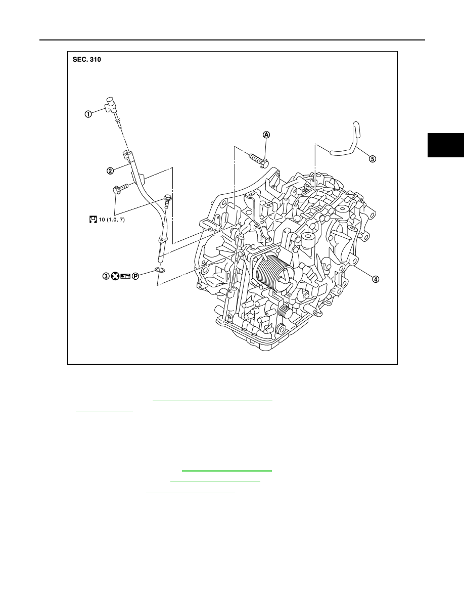
1.

CVT fluid level gauge

2.

CVT fluid charging pipe

3.

O-ring

4.

Transaxle assembly

5.

Air breather hose

A.

For tightening torque, refer to 

TM-355, "4WD : Removal and Installation"

.

Refer to 

GI-4, "Components"

 for symbols not descrived on the above.

JPDIA0103GB

TM-356

< REMOVAL AND INSTALLATION >

[CVT: RE0F10A]

TRANSAXLE ASSEMBLY

5.

Disconnect connectors (A) and then remove bracket (1).

6.

Remove air cleaner case. Refer to 

EM-144, "Exploded View"

.

7.

Drain engine coolant.

8.

Remove CVT fluid level gauge.

9.

Remove CVT fluid charging pipe from transaxle assembly.

10. Remove O-ring from CVT fluid charging pipe.

11. Disconnect fluid cooler hose from transaxle assembly. Refer to 

TM-348, "FLUID COOLER : Exploded

view"

.

12. Disconnect following harness connector and wire harness.

• CVT unit harness connector (A).
• Primary speed sensor harness connector (B).
• Secondary speed sensor harness connector (C).
• PNP switch connector (D).

13. Remove harness and clip from the transaxle assembly.

14. Remove CVT water hose. Refer to 

TM-346, "WATER HOSE :

Exploded View"

.

15. Remove control cable from transaxle assembly. Refer to 

TM-

330, "Exploded View"

.

16. Remove starter motor. Refer to 

STR-25, "MR20DE MODELS :

Exploded View"

.

17. Remove engine under cover with power tool.

18. Turn crankshaft, and remove the four tightening nuts (

) for

drive plate and torque converter.

CAUTION:

When turning crankshaft, turn it clockwise as viewed from
the front of the engine.

19. Remove exhaust front tube. Refer to 

EX-10, "Exploded View"

.

20. Separate the propeller shaft. Refer to 

DLN-110, "Exploded

View"

.

21. Remove front drive shafts. Refer to 

FAX-22, "MR20DE MOD-

ELS : Exploded View"

.

22. Remove suspension member from vehicle. Refer to 

FSU-15,

"Exploded View"

.

23. Remove transfer assembly from transaxle assembly with power tool. Refer to 

DLN-59, "CVT : Exploded

View"

.

24. Support transaxle assembly with a transmission jack.

CAUTION:

When setting the transmission jack, be careful not to collide against the drain plug.

25. Support engine assembly with a transmission jack.

CAUTION:

When setting the transmission jack, be careful not to collide against the drain plug.

26. Remove engine mounting insulator (LH). Refer to 

EM-198, "CVT : Exploded View"

.

27. Remove bolts fixing transaxle assembly to engine assembly.

28. Remove transaxle assembly from vehicle.

CAUTION:

• Secure torque converter to prevent it from dropping.
• Secure transaxle assembly to a transmission jack.

29. Remove heater thermostat. Refer to 

CO-41, "Exploded View"

.

INSTALLATION

JPDIA0240ZZ

JPDIA0113ZZ

JPDIA0114ZZ

TRANSAXLE ASSEMBLY

TM-357

< REMOVAL AND INSTALLATION >

[CVT: RE0F10A]

C

E

F

G

H

I

J

K

L

M

A

B

TM

N

O

P

Note following, and install the removed parts in the reverse order of the removal.

CAUTION:

• Check fitting of dowel pin (

) when installing transaxle

assembly to engine assembly.

• When installing transaxle assembly to the engine assembly,

attach the fixing bolts in accordance with the following.

• Set and screw in the drive plate location guide (commercial service

tool: 31197CA000) (A) onto the stud bolts for the torque converter
locate.

• When not using drive plate location guide, rotate torque converter

so that the stud bolt (A) for mounting the drive plate location guide
of torque converter aligns with the mounting position of starter
motor.

JPDIA0116ZZ

A

: Transaxle to engine

B

: Engine to transaxle

JPDIA0117ZZ

Bolt No.

A

B

Number of bolts

2

7

Bolt length “

” mm (in)

55 (2.17)

50 (1.97)

Tightening torque N·m (kg-m, ft-lb)

62 (6.3, 46)

SCIA6616J

SCIA7261J

TM-358

< REMOVAL AND INSTALLATION >

[CVT: RE0F10A]

TRANSAXLE ASSEMBLY

• Rotate crankshaft so that the hole (A) for inserting drive plate loca-

tion guide of drive plate aligns with the mounting position (B) of
starter motor.
NOTE:
When not using drive plate location guide, insert stud bolt of torque
converter into the hole of drive plate, aligning the drive plate hole
position and torque converter.

CAUTION:

Note that the stud bolt strikes the drive plate hole position is
not aligned the torque converter stud bolt.

• Align the position of tightening nuts (

) for drive plate with those

of the torque converter, and temporarily tighten the nuts. Then,
tighten the bolts with the specified torque. 

CAUTION:

• When turning crankshaft, turn it clockwise as viewed from the

front of the engine.

• When tightening the tightening nuts for the torque converter

after fixing the crankshaft pulley bolts, confirm the tightening
torque of the crankshaft pulley mounting bolts. Refer to 

EM-

163, "Removal and Installation"

.

• After converter is installed to drive plate, rotate crankshaft several turns and check that transaxle

rotates freely without binding.

4WD : Inspection

INFOID:0000000001116418

INSPECTION BE FORE INSTALLATION

• After inserting a torque converter to the CVT, check distance (A)

with in the reference value limit.

INSPECTION AFTER INSTALLATION

• After completing installation, check the following item.
- CVT fluid leakage and CVT fluid level. Refer to 

TM-314, "Inspection"

.

- CVT position. Refer to 

TM-324, "Inspection and Adjustment"

.

SCIA6617J

:51 N·m (5.2 kg-m,38 ft-lb)

JPDIA0114ZZ

B

:  Scale

C

: Straightedge

Distance (A)

: Refer to 

TM-362, "Removal and Installa-

tion"

.

JPDIA0115ZZ


Content   ..  603  604  605  606   ..