Nissan Qashqai (2007-2010). Manual - part 603
FLUID COOLER SYSTEM
TM-347
< ON-VEHICLE REPAIR >
[CVT: RE0F10A]
C
E
F
G
H
I
J
K
L
M
A
B
TM
N
O
P
4.
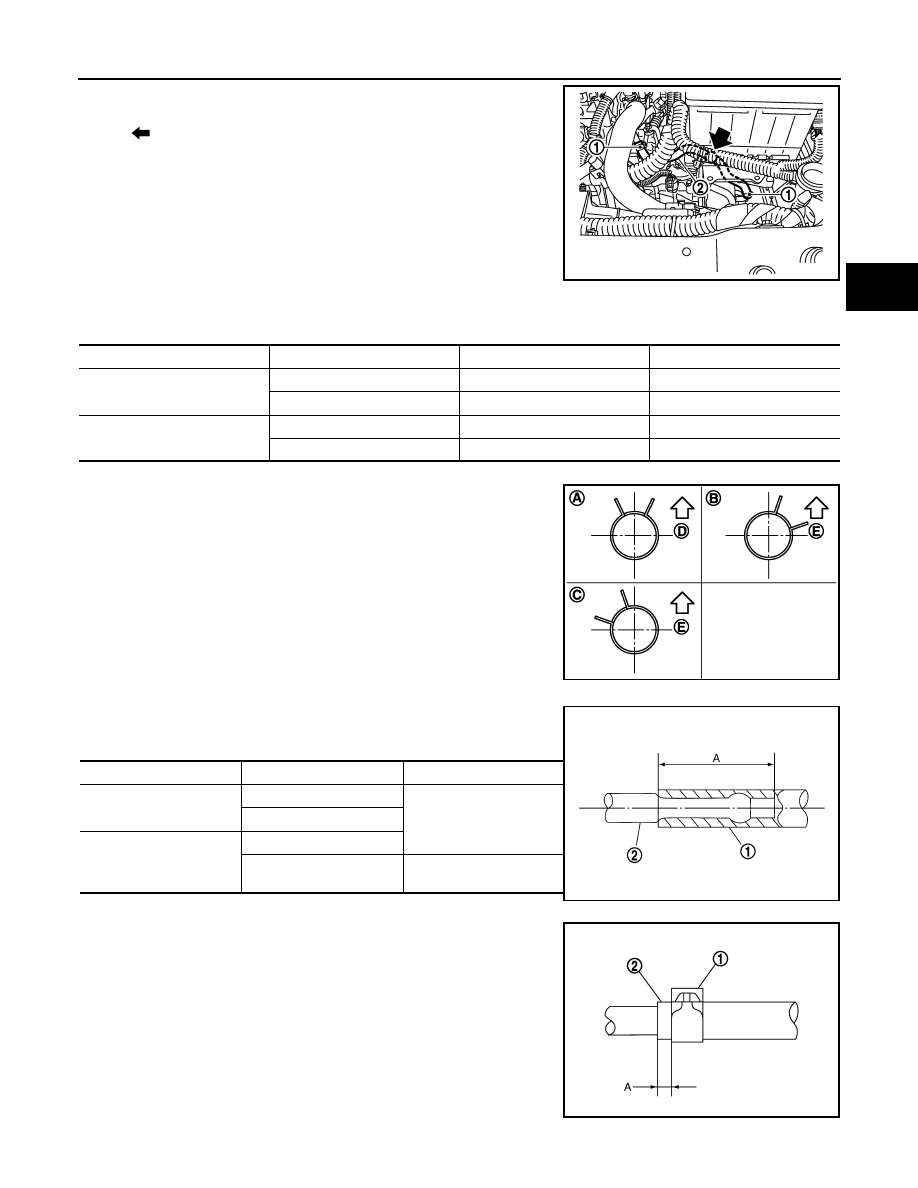
Remove hose clamp (1), and remove CVT water hose B (2).
INSTALLATION
Note the following, and install in the reverse order of removal.
*: Refer to the illustrations for the specific position each hose clamp tab.
• The illustrations indicate the view from the hose ends.
• When installing hose clamps center line of each clamp tab should
be positioned as shown in the figure.
• Insert CVT water hose according to dimension (A) described
below.
• Set hose clamps (1) from the end of fluid cooler hose (2) according
to dimension (A) described below.
• Hose clamp should not interfere with the bulge.
FLUID COOLER
: Clip
JPDIA0123ZZ
CVT water hose
Hose end
Paint mark
Position of hose clamp*
CVT water hose A
Thermostat housing
Facing upward
B
Heater thermostat
Facing forward
C
CVT water hose B
CVT fluid cooler
Facing forward
A
Water outlet
Facing forward
A
D: Front
E: Upper
JPDIA0125ZZ
(1)
(2)
Distance A
CVT water hose A
Thermostat housing
27 mm (1.06 in)
Heater thermostat
CVT water hose B
Water outlet
CVT fluid cooler
End reaches the tube
bend R position.
SCIA7203E
Dimension A
: 5 – 7 mm (0.20 – 0.28 in)
SCIA8123E