Nissan Qashqai (2007-2010). Manual - part 588
 

  Index      Nissan     Nissan Qashqai - service and repair manual 2007 - 2010 year


Search            copyright infringement  


Content   ..  586  587  588  589   ..


Nissan Qashqai (2007-2010). Manual - part 588


TCM

TM-287

< ECU DIAGNOSIS >

[CVT: RE0F10A]

C

E

F

G

H

I

J

K

L

M

A

B

TM

N

O

P

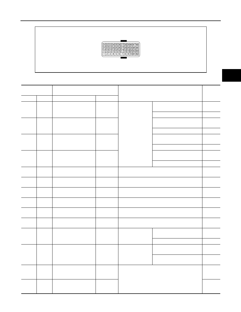
PHYSICAL VALUES

SCIA6679J

Terminal No.

(wire color)

Description

Condition

Value 

(Approx.)

+

-

Signal name

Input/Output

1

(Y/G)

Ground

R RANGE SW

Input

Ignition switch ON

Selector lever in “R” position

Battery 
voltage

Other than the above position

0 V 

2

(P/B)

Ground

N RANGE SW

Input

Selector lever in “N” position

Battery 
voltage

Other than the above position

0 V

3

(G/O)

Ground

D RANGE SW

Input

Selector lever in “D” positions

Battery 
voltage

Other than the above position

0 V

4

(GR)

Ground

L RANGE SW

Input

Selector lever in “L” position

Battery 
voltage

Other than the above position

0 V

5

(B)

Ground

Ground

Output

Always

0 V

6

(O)

Ground

K-LINE

Input/Output

7

(R/W)

Ground

Sensor ground

Input

Always

0 V

8

(G/W)

CLOCK (SEL2)

9

(L/R)

CHIP SELECT (SEL1)

10

(Y)

DATA I/O (SEL3)

11

(BR/W)

Ground

P RANGE SW

Input

Ignition switch ON

Selector lever in “P” position

Battery 
voltage

Other than the above position

0 V

13

(V)

Ground

CVT fluid temperature sen-
sor 

Output

Ignition switch ON

When CVT fluid temperature is 
20

°

C (68

°

F)

2.0 V

When CVT fluid temperature is 
80

°

C (176

°

F)

1.0 V

14

(LG)

Ground

Transmission fluid pres-
sure sensor B (Primary 
pressure sensor)

Input

“N” position idle

0.7 – 3.5 

V

15

(V/W)

Ground

Transmission fluid pres-
sure sensor A (Secondary 
pressure sensor)

Input

1.0 V

TM-288

< ECU DIAGNOSIS >

[CVT: RE0F10A]

TCM

*: A circuit tester cannot be used to test this item.

25

(W/R)

Ground

Sensor ground

Input

Always

0 V

26

(L/O)

Ground

Sensor power

Output

Ignition switch ON

5.0 V

Ignition switch OFF

0 V

27

(R/G)

Ground

Step motor D

Output

Within 2 seconds after ignition switch ON, the time 
measurement by using the pulse width measurement 
function (Hi level) of CONSULT-III.*

CAUTION:

Connect the diagnosis data link cable to the vehicle 
diagnosis connector.

10.0 

msec

28

(R)

Ground

Step motor C

Output

30.0 

msec 

29

(O/B)

Ground

Step motor B

Output

10.0 

msec

30

(G/R)

Ground

Step motor A

Output

30.0 

msec 

31

(P)

CAN-L

Input/Output

32

(L)

CAN-H

Input/Output

33

(LG/R)

Ground

Input speed sensor (Prima-
ry speed sensor)

Input

When driving [“M

1

” position, 20 km/h (12 MPH)]

800 Hz

34

(W)

Ground

Output speed sensor (Sec-
ondary speed sensor)

Input

When driving [“D” position, 20 km/h (12 MPH)]

500 Hz

37

(L/W)

Ground

Lock-up select solenoid 
valve

Output

Ignition switch ON

Selector lever in “P” or “N” posi-
tions 

Battery 
voltage

Wait at least for 5 seconds with 
the selector lever in “R” or “D” 
positions.

0 V

38

(G)

Ground

Torque converter clutch so-
lenoid valve

Output

When vehicle cruis-
es in “D” position

When CVT performs lock-up

6.0 V

When CVT does not perform 
lock-up

1.5 V

39

(W/G)

Ground

Pressure control solenoid 
valve B (Secondary pres-
sure solenoid valve)

Output

“P” or “N” position 
idle

 Release your foot from the ac-
celerator pedal.

5.0 – 7.0 

V

 Press the accelerator pedal all 
the way down.

3.0 – 4.0 

V

40

(R/Y)

Ground

Pressure control solenoid 
valve A (Line pressure so-
lenoid valve)

Output

 Release your foot from the ac-
celerator pedal.

5.0 – 7.0 

V

 Press the accelerator pedal all 
the way down.

1.0 V

42

(B)

Ground

Ground

Output

Always

0 V

45

(R/B)

Ground

Power supply
(memory back-up)

Input

Always

Battery 
voltage

46

(Y/R)

Ground

Power supply

Input

Ignition switch ON

Battery 
voltage

Ignition switch OFF

0 V

47

(R/B)

Ground

Power supply
(memory back-up)

Input

Always

Battery 
voltage

48

(Y/R)

Ground

Power supply

Input

Ignition switch ON

Battery 
voltage

Ignition switch OFF

0 V

Terminal No.

(wire color)

Description

Condition

Value 

(Approx.)

+

-

Signal name

Input/Output

TCM

TM-289

< ECU DIAGNOSIS >

[CVT: RE0F10A]

C

E

F

G

H

I

J

K

L

M

A

B

TM

N

O

P

Wiring Diagram - CVT CONTROL SYSTEM -

INFOID:0000000000988741

JCDWA0068GB

TM-290

< ECU DIAGNOSIS >

[CVT: RE0F10A]

TCM

JCDWA0069GB


Content   ..  586  587  588  589   ..