Nissan Qashqai (2007-2010). Manual - part 566
 

  Index      Nissan     Nissan Qashqai - service and repair manual 2007 - 2010 year


Search            copyright infringement  


Content   ..  564  565  566  567   ..


Nissan Qashqai (2007-2010). Manual - part 566


HYDRAULIC CONTROL SYSTEM

TM-199

< FUNCTION DIAGNOSIS >

[CVT: RE0F10A]

C

E

F

G

H

I

J

K

L

M

A

B

TM

N

O

P

Component Description

INFOID:0000000000988613

TRANSAXLE ASSEMBLY

JPDIA0129GB

TM-200

< FUNCTION DIAGNOSIS >

[CVT: RE0F10A]

HYDRAULIC CONTROL SYSTEM

EXCEPT TRANSAXLE ASSEMBLY

Name

Function

Torque converter regulator valve

Optimizes the supply pressure for the torque converter depending on driving conditions.

Pressure regulator valve

Optimizes the discharge pressure from the oil pump depending on driving conditions.

TCC control valve

• Activates or deactivate the lock-up.
• Lock-up smoothly by opening lock-up operation excessively.

TCC solenoid valve

TM-242

Shift control valve

Controls flow-in/out of line pressure from the primary pulley depending on the stroke dif-
ference between the stepping motor and the primary pulley.

Secondary valve

Controls the line pressure from the secondary pulley depending on operating conditions.

Clutch regulator valve

Adjusts the clutch operating pressure depending on operating conditions. 

Secondary pressure solenoid valve

TM-250

Line pressure solenoid valve

TM-244

Step motor

TM-276

Manual valve

Transmits the clutch operating pressure to each circuit in accordance with the selected 
position.

Select control valve

Engages forward clutch, reverse brake smoothly depending on select operation.

Select switch valve

Switches torque converter clutch solenoid valve control pressure use to torque converter 
clutch control valve or select control valve.

Lock-up select solenoid valve

TM-273

Primary speed sensor

TM-231

Secondary speed sensor

TM-234

PNP switch

TM-231

Primary pulley

TM-195

Secondary pulley

Forward clutch

Torque converter

Name

Function

TCM

Judges the vehicle driving status according to the signal from each sensor and controls 
the non-step transmission mechanism properly.

Accelerator pedal position sensor

TM-267

CONTROL SYSTEM

TM-201

< FUNCTION DIAGNOSIS >

[CVT: RE0F10A]

C

E

F

G

H

I

J

K

L

M

A

B

TM

N

O

P

CONTROL SYSTEM

System Diagram

INFOID:0000000000988614

System Description

INFOID:0000000000988615

The function of the TCM is to:
• Receive input signals sent from various switches and sensors.
• Determine required line pressure, shifting point, and lock-up operation.
• Send required output signals to the step motor and the respective solenoids.

CONTROL SYSTEM OUTLINE 

The CVT senses vehicle operating conditions through various sensors. It always controls the optimum shift
position and reduces shifting and lock-up shocks.

INPUT/OUTPUT SIGNAL OF TCM

JPDIA0185GB

SENSORS (or SIGNAL)

TCM

ACTUATORS

PNP switch
Accelerator pedal position signal
Closed throttle position signal
Engine speed signal
CVT fluid temperature sensor
Vehicle speed signal
Manual mode signal
Stop lamp switch signal
Primary speed sensor
Secondary speed sensor
Primary pressure sensor
Secondary pressure sensor

Shift control
Line pressure control
Primary pressure control
Secondary pressure control
Lock-up control
Engine brake control
Vehicle speed control
Fail-safe control
Self-diagnosis
CONSULT-III communication 
line
Duet-EA control
CAN system
On board diagnosis

Step motor 
Torque converter clutch solenoid 
valve
Lock-up select solenoid valve
Line pressure solenoid valve
Secondary pressure solenoid 
valve
Manual mode indicator
Shift position indicator
CVT indicator lamp

TM-202

< FUNCTION DIAGNOSIS >

[CVT: RE0F10A]

CONTROL SYSTEM

*

1

: Input by CAN communications.

*

2

: If these input and output signals are different, the TCM triggers the fail-safe function.

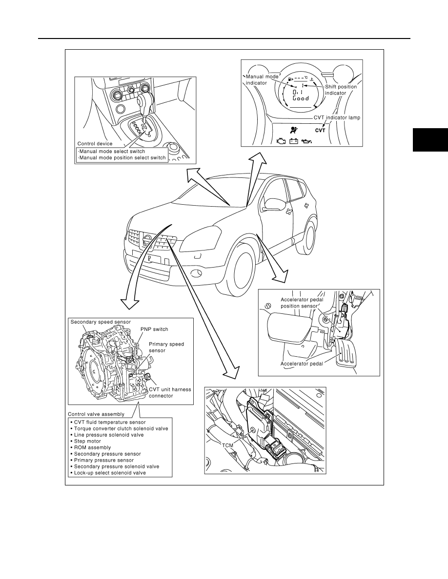
Component Parts Location

INFOID:0000000000988616

Control item

Fluid

 pressure

 control

Select con-

trol

Shift control

Lock-up 

control

CAN com-

munication 

control

Fail-safe 

function

(

*

2)

Input

PNP  switch

X

X

X

X

X

X

Accelerator pedal position signal 

(

*

1)

X

X

X

X

X

X

Closed throttle position signal

(

*

1)

X

X

X

X

Engine speed signal

(

*

1)

X

X

X

X

X

CVT fluid temperature sensor

X

X

X

X

X

Manual mode signal

(

*

1)

X

X

X

X

X

Stop lamp switch signal

(

*

1)

X

X

X

X

Primary speed sensor

X

X

X

X

X

Secondary speed sensor

X

X

X

X

X

X

Primary pressure sensor

X

X

Secondary pressure sensor

X

X

X

Out-
put

Step motor

X

X

TCC solenoid valve

X

X

X

Lock-up select solenoid valve

X

X

X

Line pressure solenoid valve

X

X

X

X

Secondary pressure solenoid valve

X

X

X


Content   ..  564  565  566  567   ..