Nissan Qashqai (2007-2010). Manual - part 296
 

  Index      Nissan     Nissan Qashqai - service and repair manual 2007 - 2010 year


Search            copyright infringement  


Content   ..  294  295  296  297   ..


Nissan Qashqai (2007-2010). Manual - part 296


INTAKE VALVE TIMING CONTROL

EC-703

< FUNCTION DIAGNOSIS >

[MR20DE (WITH EURO-OBD)]

C

D

E

F

G

H

I

J

K

L

M

A

EC

N

P

O

Component Description

INFOID:0000000000936636

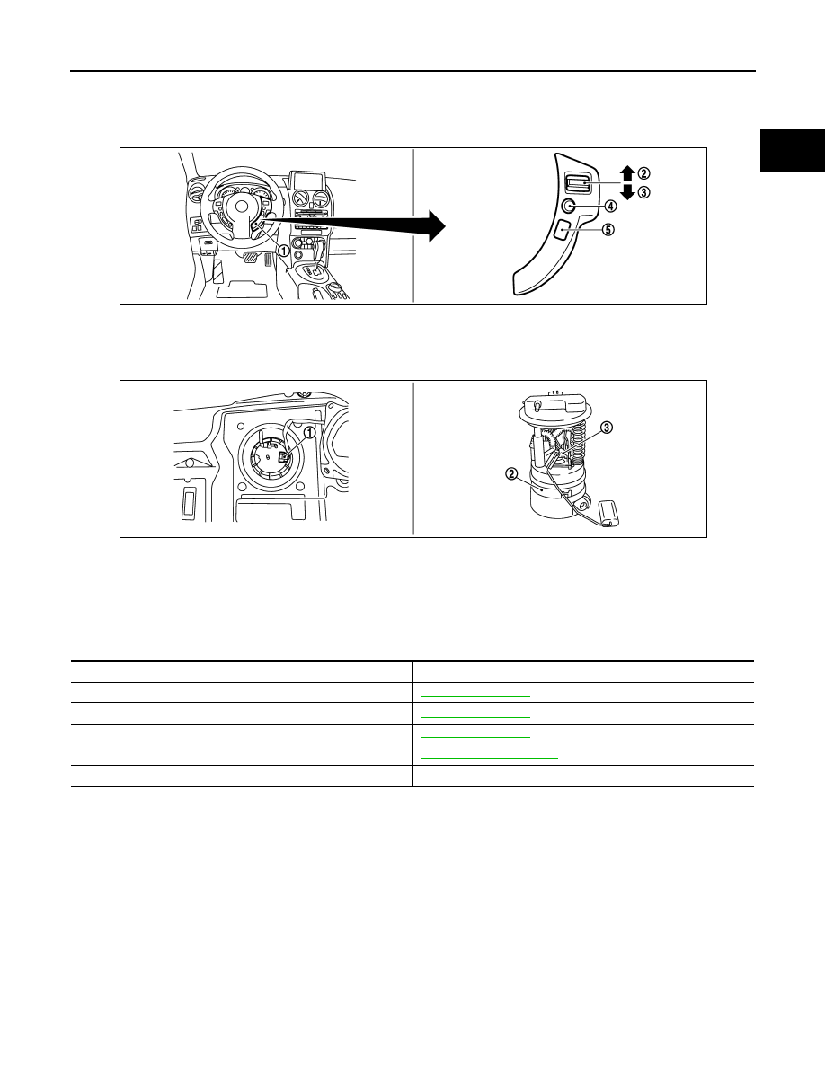
1.

Stop lamp switch

2.

ASCD brake switch

3.

Accelerator pedal position sensor

1.

ASDC steering switch

2.

CANSEL switch

3.

RESUME/ACCCELERATE switch

4.

SET/COAST switch

5.

MAIN SWITCH

6.

1.

Fuel level sensor unit and fuel pump 
harness connector

2.

Fuel level sensor unit and fuel pump 3.

Fuel pressure regulator

JMBIA0349ZZ

JMBIA0346ZZ

Component

Reference

Camshaft position sensor (PHASE)

EC-813, "Description"

Crankshaft position sensor (POS)

EC-809, "Description"

Engine coolant temperature sensor

EC-754, "Description"

Intake valve timing control solenoid valve

EC-700, "System Diagram"

Vehicle speed sensor

EC-825, "Description"

EC-704

< FUNCTION DIAGNOSIS >

[MR20DE (WITH EURO-OBD)]

ON BOARD DIAGNOSTIC (OBD) SYSTEM

ON BOARD DIAGNOSTIC (OBD) SYSTEM

Diagnosis Description

INFOID:0000000000936637

INTRODUCTION

The ECM has an on board diagnostic system, which detects malfunctions related to engine sensors or actua-
tors. The ECM also records various emission-related diagnostic information including:

The above information can be checked using procedures listed in the table below.

×

: Applicable

—: Not applicable

*: When DTC and 1st trip DTC simultaneously appear on the display, they cannot be clearly distinguished from each other.

The malfunction indicator (MI) on the instrument panel lights up when the same malfunction is detected in two
consecutive trips (Two trip detection logic), or when the ECM enters fail-safe mode. (Refer to 

EC-959,

"Fail Safe"

.)

TWO TRIP DETECTION LOGIC

When a malfunction is detected for the first time, 1st trip DTC and 1st trip Freeze Frame data are stored in the
ECM memory. The MI will not light up at this stage. <1st trip>
If the same malfunction is detected again during the next drive, the DTC and Freeze Frame data are stored in
the ECM memory, and the MI lights up. The MI lights up at the same time when the DTC is stored. <2nd trip>
The “trip” in the “Two Trip Detection Logic” means a driving mode in which self-diagnosis is performed during
vehicle operation. Specific on board diagnostic items will cause the ECM to light up or blink the MI, and store
DTC and Freeze Frame data, even in the 1st trip, as shown below.

×

: Applicable

—: Not applicable

DTC AND FREEZE FRAME DATA

DTC and 1st Trip DTC

Emission-related diagnostic information

Diagnostic service

Diagnostic Trouble Code (DTC)

Service $03 of SAE J1979

Freeze Frame data

Service $02 of SAE J1979

System Readiness Test (SRT) code

Service $01 of SAE J1979

1st Trip Diagnostic Trouble Code (1st Trip DTC)

Service $07 of SAE J1979

1st Trip Freeze Frame data

Test values and Test limits

Service $06 of SAE J1979

Calibration ID

Service $09 of SAE J1979

DTC

1st trip DTC

Freeze Frame 

data

1st trip Freeze 

Frame data

SRT code

Test value

CONSULT-III

×

×

×

×

×

GST

×

×

×

×

×

ECM

×

×

*

Items

MI

DTC

1st trip DTC

1st trip

2nd trip 

1st trip 

displaying

2nd trip 

displaying

1st trip 

displaying

2nd trip 

display-

ing

Blinking

Lighting 

up

Blinking

Lighting 

up

Misfire (Possible three way catalyst 
damage) — DTC: P0300 - P0304 is 
being detected

×

×

Misfire (Possible three way catalyst 
damage) — DTC: P0300 - P0304 is 
being detected

×

×

One trip detection diagnoses (Re-
fer to 

EC-962, "DTC Index"

.)

×

×

Except above

×

×

×

ON BOARD DIAGNOSTIC (OBD) SYSTEM

EC-705

< FUNCTION DIAGNOSIS >

[MR20DE (WITH EURO-OBD)]

C

D

E

F

G

H

I

J

K

L

M

A

EC

N

P

O

The 1st trip DTC (whose number is the same as the DTC number) is displayed for the latest self-diagnostic
result obtained. If the ECM memory was cleared previously, and the 1st trip DTC did not reoccur, the 1st trip
DTC will not be displayed.
If a malfunction is detected during the 1st trip, the 1st trip DTC is stored in the ECM memory. The MI will not
light up (two trip detection logic). If the same malfunction is not detected in the 2nd trip (meeting the required
driving pattern), the 1st trip DTC is cleared from the ECM memory. If the same malfunction is detected in the
2nd trip, both the 1st trip DTC and DTC are stored in the ECM memory and the MI lights up. In other words,
the DTC is stored in the ECM memory and the MI lights up when the same malfunction occurs in two consec-
utive trips. If a 1st trip DTC is stored and a non-diagnostic operation is performed between the 1st and 2nd
trips, only the 1st trip DTC will continue to be stored. For malfunctions that blink or light up the MI during the
1st trip, the DTC and 1st trip DTC are stored in the ECM memory.
Procedures for clearing the DTC and the 1st trip DTC from the ECM memory are described in “HOW TO
ERASE EMISSION-RELATED DIAGNOSTIC INFORMATION”.
For malfunctions in which 1st trip DTCs are displayed, refer to “EMISSION-RELATED DIAGNOSTIC INFOR-
MATION ITEMS”. These items are required by legal regulations to continuously monitor the system/compo-
nent. In addition, the items monitored non-continuously are also displayed on CONSULT-III.
1st trip DTC is specified in Service $07 of SAE J1979. 1st trip DTC detection occurs without lighting up the MI
and therefore does not warn the driver of a malfunction. However, 1st trip DTC detection will not prevent the
vehicle from being tested, for example during Inspection/Maintenance (I/M) tests.
When a 1st trip DTC is detected, check, print out or write down and erase (1st trip) DTC and Freeze Frame
data as specified in Work Flow procedure Step 2, refer to 

EC-638, "Work Flow"

. Then perform DTC CONFIR-

MATION PROCEDURE or Component Function Check to try to duplicate the malfunction. If the malfunction is
duplicated, the item requires repair.

Freeze Frame Data and 1st Trip Freeze Frame Data

The ECM records the driving conditions such as fuel system status, calculated load value, engine coolant tem-
perature, short term fuel trim, long term fuel trim, engine speed, vehicle speed, absolute throttle position, base
fuel schedule and intake air temperature at the moment a malfunction is detected.
Data which are stored in the ECM memory, along with the 1st trip DTC, are called 1st trip freeze frame data.
The data, stored together with the DTC data, are called freeze frame data and displayed on CONSULT-III or
GST. The 1st trip freeze frame data can only be displayed on the CONSULT-III screen, not on the GST.
Only one set of freeze frame data (either 1st trip freeze frame data or freeze frame data) can be stored in the
ECM. 1st trip freeze frame data is stored in the ECM memory along with the 1st trip DTC. There is no priority
for 1st trip freeze frame data and it is updated each time a different 1st trip DTC is detected. However, once
freeze frame data (2nd trip detection/MI on) is stored in the ECM memory, 1st trip freeze frame data is no
longer stored. Remember, only one set of freeze frame data can be stored in the ECM. The ECM has the fol-
lowing priorities to update the data.

For example, the EGR malfunction (Priority: 2) was detected and the freeze frame data was stored in the 2nd
trip. After that when the misfire (Priority: 1) is detected in another trip, the freeze frame data will be updated
from the EGR malfunction to the misfire. The 1st trip freeze frame data is updated each time a different mal-
function is detected. There is no priority for 1st trip freeze frame data. However, once freeze frame data is
stored in the ECM memory, 1st trip freeze data is no longer stored (because only one freeze frame data or 1st
trip freeze frame data can be stored in the ECM). If freeze frame data is stored in the ECM memory and freeze
frame data with the same priority occurs later, the first (original) freeze frame data remains unchanged in the
ECM memory.
Both 1st trip freeze frame data and freeze frame data (along with the DTCs) are cleared when the ECM mem-
ory is erased. Procedures for clearing the ECM memory are described in “HOW TO ERASE EMISSION-
RELATED DIAGNOSTIC INFORMATION”.

How to Read DTC and 1st Trip DTC

With CONSULT-III
With GST

CONSULT-III or GST (Generic Scan Tool) Examples: P0340, P1148, P1706, etc.
These DTCs are prescribed by SAE J2012.

Priority

Items

1

Freeze frame data

Misfire — DTC: P0300 - P0304
Fuel Injection System Function — DTC: P0171, P0172

2

Except the above items (Includes CVT related items)

3

1st trip freeze frame data

EC-706

< FUNCTION DIAGNOSIS >

[MR20DE (WITH EURO-OBD)]

ON BOARD DIAGNOSTIC (OBD) SYSTEM

(CONSULT-III also displays the malfunctioning component or system.)

No Tools

The number of blinks of the MI in the Diagnostic Test Mode II (Self-Diagnostic Results) indicates the DTC.
Example: 0340, 1148, 1706, etc.
These DTCs are controlled by NISSAN.
• 1st trip DTC No. is the same as DTC No.
• Output of a DTC indicates a malfunction. However, GST or the Diagnostic Test Mode II do not indi-

cate whether the malfunction is still occurring or has occurred in the past and has returned to nor-
mal. CONSULT-III can identify malfunction status as shown below. Therefore, using CONSULT-III (if
available) is recommended.

DTC or 1st trip DTC of a malfunction is displayed in “SELF-DIAGNOSTIC RESULTS” mode of CONSULT-III.
Time data indicates how many times the vehicle was driven after the last detection of a DTC.
If the DTC is being detected currently, the time data will be [0].
If a 1st trip DTC is stored in the ECM, the time data will be [1t].

How to Erase DTC and 1st Trip DTC

 With CONSULT-III

The emission related diagnostic information in the ECM can be erased by selecting “All Erase” in the “Descrip-
tion” of “FINAL CHECK” mode with CONSULT-III.

 With GST

The emission related diagnostic information in the ECM can be erased by selecting Service $04 with GST.
NOTE:
If the DTC is not for CVT related items (see 

EC-962, "DTC Index"

), skip step 2.

1.

If the ignition switch stays ON after repair work, be sure to turn ignition switch OFF once. Wait at least 10
seconds and then turn it ON (engine stopped) again.

2.

Perform 

TM-214, "Diagnosis Description"

. (The DTC in TCM will be erased)

3.

Select Service $04 with GST (Generic Scan Tool).

 No Tools

NOTE:
If the DTC is not for CVT related items (see 

EC-962, "DTC Index"

), skip step 2.

1.

If the ignition switch stays ON after repair work, be sure to turn ignition switch OFF once.
Wait at least 10 seconds and then turn it ON (engine stopped) again.

2.

Perform 

TM-214, "Diagnosis Description"

. (The DTC in the TCM will be erased.)

3.

Change the diagnostic test mode from Mode II to Mode I by depressing the accelerator pedal.

• If the battery is disconnected, the emission-related diagnostic information will be lost within 24

hours.

• The following data are cleared when the ECM memory is erased.
- Diagnostic trouble codes
- 1st trip diagnostic trouble codes
- Freeze frame data
- 1st trip freeze frame data
- System readiness test (SRT) codes
- Test values
Actual work procedures are explained using a DTC as an example. Be careful so that not only the DTC, but all
of the data listed above, are cleared from the ECM memory during work procedures.

SYSTEM READINESS TEST (SRT) CODE

System Readiness Test (SRT) code is specified in Service $01 of SAE J1979.
As part of an enhanced emissions test for Inspection & Maintenance (I/M), certain states require the status of
SRT be used to indicate whether the ECM has completed self-diagnosis of major emission systems and com-
ponents. Completion must be verified in order for the emissions inspection to proceed.
If a vehicle is rejected for a State emissions inspection due to one or more SRT items indicating “INCMP”, use
the information in this Service Manual to set the SRT to “CMPLT”.
In most cases the ECM will automatically complete its self-diagnosis cycle during normal usage, and the SRT
status will indicate “CMPLT” for each application system. Once set as “CMPLT”, the SRT status remains
“CMPLT” until the self-diagnosis memory is erased.
Occasionally, certain portions of the self-diagnostic test may not be completed as a result of the customer's
normal driving pattern; the SRT will indicate “INCMP” for these items.
NOTE:
The SRT will also indicate “INCMP” if the self-diagnosis memory is erased for any reason or if the ECM mem-
ory power supply is interrupted for several hours.


Content   ..  294  295  296  297   ..