Nissan Qashqai (2007-2010). Manual - part 291
COOLING FAN CONTROL
EC-683
< FUNCTION DIAGNOSIS >
[MR20DE (WITH EURO-OBD)]
C
D
E
F
G
H
I
J
K
L
M
A
EC
N
P
O
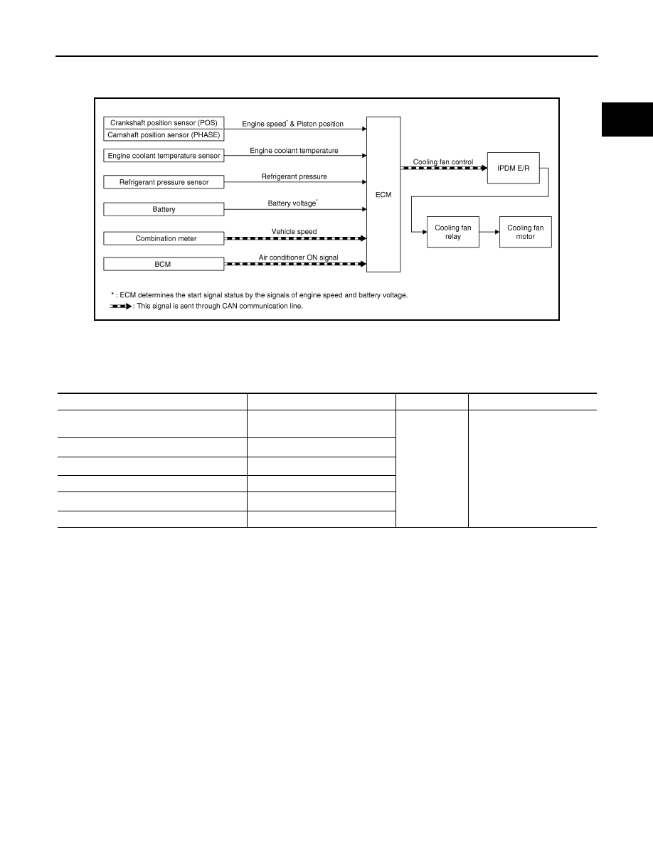
COOLING FAN CONTROL
System Diagram
INFOID:0000000000936625
System Description
INFOID:0000000000936626
INPUT/OUTPUT SIGNAL CHART
*1: The ECM determines the start signal status by the signals of engine speed and battery voltage.
*2: This signal is sent to ECM through CAN communication line.
SYSTEM DESCRIPTION
ECM controls cooling fan speed corresponding to vehicle speed, engine coolant temperature, refrigerant pres-
sure, air conditioner ON signal. Then control system has 3-step control [HIGH/LOW/OFF].
JMBIA0177GB
Sensor
Input signal to ECM
ECM function
Actuator
Crankshaft position sensor (POS)
Camshaft position sensor (PHASE)
Engine speed*
1
Cooling fan
control
IPDM E/R
↓
Cooling fan relay
↓
Cooling fan motor
Battery
Battery voltage*
1
Combination meter
Vehicle speed*
2
Engine coolant temperature sensor
Engine coolant temperature
BCM
Air conditioner ON signal*
2
Refrigerant pressure sensor
Refrigerant pressure