Content .. 1478 1479 1480 1481 ..
Nissan Qashqai (2007-2010). Manual - part 1480
BCS-10
< FUNCTION DIAGNOSIS >
COMBINATION SWITCH READING SYSTEM
NOTE:
Headlamp has a dual system switch.
COMBINATION SWITCH READING FUNCTION
Description
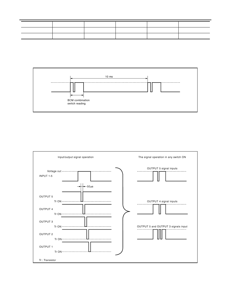
• BCM reads the status of the combination switch at 10 ms interval normally.
NOTE:
BCM reads the status of the combination switch at 20 ms interval when BCM is controlled at low power con-
sumption control mode.
• BCM operates as follows and judges the status of the combination switch.
- INPUT 1 - 5 outputs the voltage waveforms of 5 systems simultaneously.
- It operates the transistor on OUTPUT side in the following order: OUTPUT 5
→
4
→
3
→
2
→
1.
- The voltage waveform of INPUT corresponding to the formed circuit changes according to the operation of
the transistor on OUTPUT side if any (1 or more) switches are ON.
- It reads this change of the voltage as the status signal of the combination switch.
Operation Example
In the following operation example, the combination of the status signals of the combination switch is replaced
as follows: INPUT 1 - 5 to “1 - 5” and OUTPUT 1 - 5 to “A - E”.
Example 1: When a switch (TURN RH switch) is turned ON
INPUT 4
RR WIPER INT
INT VOLUME 3
AUTO LIGHT
—
TAIL LAMP
INPUT 5
INT VOLUME 2
RR WIPER
RR FOG
FR FOG
—
System
OUTPUT 1
OUTPUT 2
OUTPUT 3
OUTPUT 4
OUTPUT 5
JPMIA0067GB
JPMIA0068GB