Nissan Qashqai (2007-2010). Manual - part 1412


  Index      Nissan     Nissan Qashqai - service and repair manual 2007 - 2010 year


Search            copyright infringement  


Content   ..  1410  1411  1412  1413   ..


Nissan Qashqai (2007-2010). Manual - part 1412


INTERIOR ROOM LAMP BATTERY SAVER SYSTEM

INL-11

< FUNCTION DIAGNOSIS >

C

D

E

F

G

H

I

J

K

M

A

B

INL

N

O

P

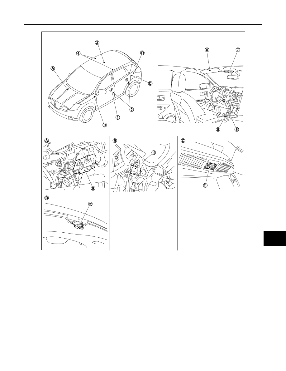
Component Description

INFOID:0000000001033366

1.

Request switch

2.

Door switch

3.

Room lamp
(Without glass top roof)

4.

Personal lamp
(With glass top roof)

5.

Door lock and unlock switch

6.

• Key switch
• Push switch (With Intelligent Key)

7.

Map lamp

8.

Vanity mirror lamp

9.

BCM

10.

Intelligent Key unit

11.

Luggage room lamp

12. Back door switch

A.

Over the glove box

B.

Over the instrument lower panel 
(driver side)

C.

Luggage room upward

D.

Back door lock assembly

JSLIA0077ZZ

INL-12

< FUNCTION DIAGNOSIS >

INTERIOR ROOM LAMP BATTERY SAVER SYSTEM

Part

Description

BCM

Operates the interior room lamp battery saver depending on the vehicle condition to 
cut the interior room lamp power supply. 

Remote keyless entry receiver
(integrated in the BCM)

Receives the lock/unlock signal from Keyfob.

Intelligent Key unit

Transmits the lock/unlock signal and push switch signal to BCM with CAN communi-
cation.

Door lock and unlock switch

Inputs the lock/unlock signal to BCM.

• Door switch
• Back door switch

Inputs the door switch signal to BCM.

Key switch

Inputs the key switch signal to BCM.

ILLUMINATION CONTROL SYSTEM

INL-13

< FUNCTION DIAGNOSIS >

C

D

E

F

G

H

I

J

K

M

A

B

INL

N

O

P

ILLUMINATION CONTROL SYSTEM

System Diagram

INFOID:0000000001033367

System Description

INFOID:0000000001033368

OUTLINE

Each illumination lamp is controlled by each function of BCM and IPDM E/R.

Control by BCM

• Combination switch reading function
• Headlamp control function

Control by IPDM E/R

• Relay control function

ILLUMINATION CONTROL

• BCM detects the combination switch condition by the combination switch reading function.
• BCM transmits position light request signal to IPDM E/R and combination meter according to tail lamp ON

condition.

Tail lamp ON condition

- Lighting switch 1ST
- Lighting switch 2ND
- Lighting switch AUTO, and the auto light function ON judgment (With auto light system)
• IPDM E/R turns the integrated tail lamp relay ON according to position light request signal. It provides the

power supply to each illumination lamp. 

• Combination meter illuminates the meter illumination according to position light request signal.

Component Parts Location

INFOID:0000000001033369

JSLIA0087GB

INL-14

< FUNCTION DIAGNOSIS >

ILLUMINATION CONTROL SYSTEM

Component Description

INFOID:0000000001033370

1.

Combination switch

2.

Combination meter

3.

BCM

4.

IPDM E/R

A

Over the glove box

B.

Engine room (left side)

JPLIA0199ZZ

Part

Description

BCM

• Judges each switch condition by the combination switch reading function.
• Judges the illumination lamp ON/OFF status depending on the vehicle condition. 

And then it transmits position light request signal to IPDM E/R and combination 
meter (with CAN communication). 

IPDM E/R

Controls the integrated relay according to the request from BCM (with CAN communi-
cation).

COMBINATION METER

Illuminates the meter illumination according to the request from BCM (with CAN com-
munication).

Combination switch
(Lighting & turn signal switch)

Refer to 

BCS-9, "System Diagram"

.


Content   ..  1410  1411  1412  1413   ..