Content .. 1375 1376 1377 1378 ..
Nissan Qashqai (2007-2010). Manual - part 1377
POWER SUPPLY AND GROUND CIRCUIT
EXL-213
< COMPONENT DIAGNOSIS >
[HALOGEN TYPE]
C
D
E
F
G
H
I
J
K
M
A
B
EXL
N
O
P
COMPONENT DIAGNOSIS
POWER SUPPLY AND GROUND CIRCUIT
BCM (BODY CONTROL MODULE)
BCM (BODY CONTROL MODULE) : Diagnosis Procedure
INFOID:0000000001099350
1.
CHECK FUSES AND FUSIBLE LINK
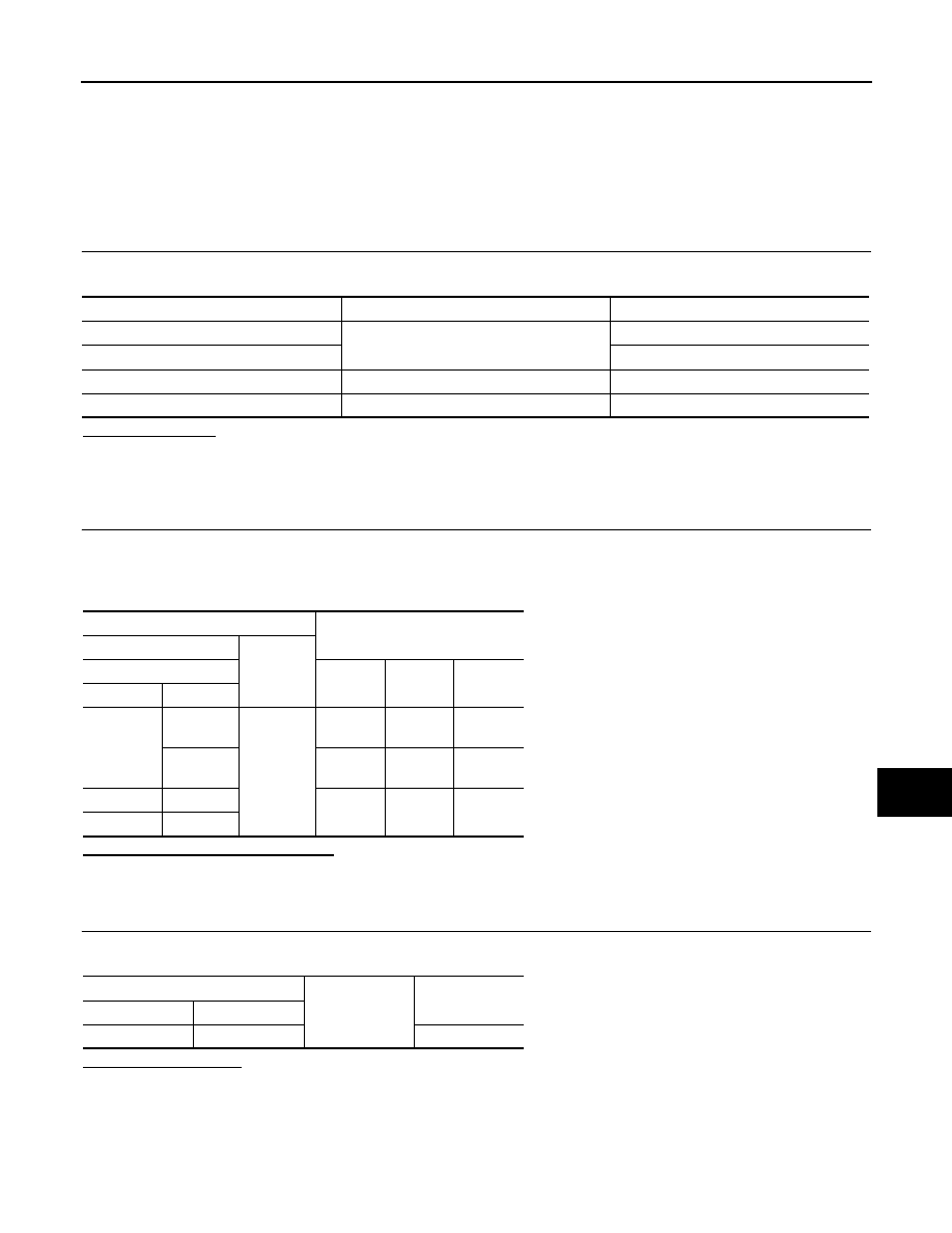
Check that the following fuses and fusible link are not fusing.
Is the fuse fusing?
YES
>> Replace the blown fuse or fusible link after repairing the affected circuit if a fuse or fusible link is
blown.
NO
>> GO TO 2.
2.
CHECK POWER SUPPLY CIRCUIT
1.
Turn ignition switch OFF.
2.
Disconnect BCM connectors.
3.
Check voltage between BCM harness connector and ground.
Is the measurement value normal?
YES
>> GO TO 3.
NO
>> Repair harness or connector.
3.
CHECK GROUND CIRCUIT
Check continuity between BCM harness connector and ground.
Does continuity exist?
YES
>> INSPECTION END
NO
>> Repair harness or connector.
IPDM E/R (INTELLIGENT POWER DISTRIBUTION MODULE ENGINE ROOM)
IPDM E/R (INTELLIGENT POWER DISTRIBUTION MODULE ENGINE ROOM) : Di-
Terminal No.
Signal name
Fuses and fusible link No.
41
Battery power supply
9
57
J
37
ACC power supply
5
38
Ignition power supply
4
Terminals
Ignition switch position
(+)
(
−
)
BCM
OFF
ACC
ON
Connector
Terminal
M65
37
Ground
Approx.
0 V
Battery
voltage
Battery
voltage
38
Approx.
0 V
Approx.
0 V
Battery
voltage
M66
41
Battery
voltage
Battery
voltage
Battery
voltage
M67
57
BCM
Ground
Continuity
Connector
Terminal
M67
55
Existed