Nissan Qashqai (2007-2010). Manual - part 1111


  Index      Nissan     Nissan Qashqai - service and repair manual 2007 - 2010 year


Search            copyright infringement  


Content   ..  1109  1110  1111  1112   ..


Nissan Qashqai (2007-2010). Manual - part 1111


BACK DOOR

DLK-523

< ON-VEHICLE REPAIR >

[WITH I-KEY & SUPER LOCK]

C

D

E

F

G

H

I

J

L

M

A

B

DLK

N

O

P

BACK DOOR HINGE : Removal and Installation

INFOID:0000000001102424

REMOVAL

1.

Remove the back door assembly. Refer to 

DLK-248, "BACK DOOR ASSEMBLY : Removal and Installa-

tion"

2.

Remove upper side of the back door weatherstrip. Refer to 

DLK-254, "BACK DOOR WEATHER-STRIP :

Removal and Installation"

.

3.

Remove rear seat belt cover. Refer to 

INT-21, "Removal and Installation"

.

4.

Using remover tool, remove the headlining clip at the rear side of the headlining.
 Refer to 

INT-20, "Exploded View"

.

5.

Remove the rear side of the headlining. 

6.

Remove the back door hinge mounting nuts (body side), and then remove the back door hinge.

INSTALLATION

Install in the reverse order of removal.

CAUTION:

• When removing and installing the back door assembly, perform the fitting adjustment. Refer to 

DLK-

250, "BACK DOOR ASSEMBLY : Adjustment"

.

• After installation, apply touch-up paint (the body color) onto the head of the hinge mounting nuts.
• Check the hinge rotating part for poor lubrication. If necessary, apply body grease.
• Check the back door open/close operation after installation.

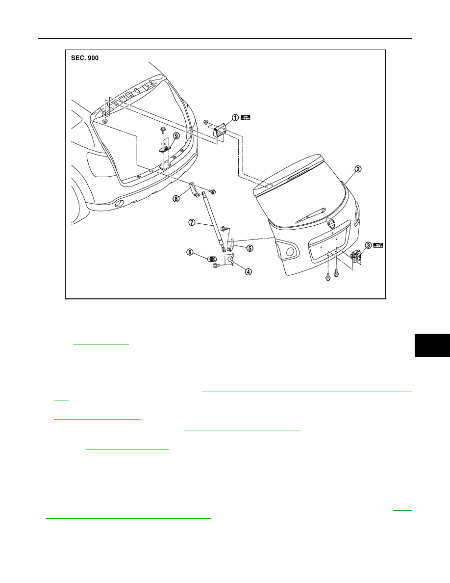
BACK DOOR STAY

1.

Back door hinge

2.

Back door assembly

3.

Back door lock assembly

4.

Bumper rubber bracket

5.

Back door stay bracket (lower)

6.

Bumper rubber

7.

Back door stay

8.

Back door stay bracket (upper)

9.

Back door striker

Refer to 

GI-4, "Components"

 for symbols in the figure.

JMKIA0186ZZ

DLK-524

< ON-VEHICLE REPAIR >

[WITH I-KEY & SUPER LOCK]

BACK DOOR

BACK DOOR STAY : Exploded View

INFOID:0000000001098532

BACK DOOR STAY : Removal and Installation

INFOID:0000000001098535

REMOVAL

1.

Remove the stud ball (upper/lower), and then remove the back door stay. 

2.

Remove the mounting bolts, and then remove the back door stay bracket (upper/lower).

INSTALLATION

Install in the reverse order of removal.

CAUTION:

Check the back door open/close operation after installation.

BACK DOOR WEATHER-STRIP

BACK DOOR WEATHER-STRIP : Exploded View

INFOID:0000000001098536

REMOVAL

1.

Back door hinge

2.

Back door assembly

3.

Back door lock assembly

4.

Bumper rubber bracket

5.

Back door stay bracket (lower)

6.

Bumper rubber

7.

Back door stay

8.

Back door stay bracket (upper)

9.

Back door striker

Refer to 

GI-4, "Components"

 for symbols in the figure.

JMKIA0186ZZ

BACK DOOR

DLK-525

< ON-VEHICLE REPAIR >

[WITH I-KEY & SUPER LOCK]

C

D

E

F

G

H

I

J

L

M

A

B

DLK

N

O

P

BACK DOOR WEATHER-STRIP : Removal and Installation

INFOID:0000000001098538

REMOVAL

Pull up and remove engagement with body from the weatherstrip joint.

CAUTION:

After removal, do not pull strongly on the weather-strip.

INSTALLATION

1.

Working from the upper section, align the weatherstrip mark with vehicle center position mark and install
the weatherstrip onto the vehicle.

2.

For the lower section, align the weatherstrip seam with center of the back door striker.

3.

After installation, pull the weatherstrip gently to ensure that there is no loose section.
NOTE:
Make sure that the weatherstrip is fit tlightly at each corner and the luggage rear plate.

1.

Back door weatherstrip

A.

Mark (upper)

B.

Mark (lower)

JMKIA0184ZZ

DLK-526

< ON-VEHICLE REPAIR >

[WITH I-KEY & SUPER LOCK]

FRONT DOOR LOCK

FRONT DOOR LOCK

DOOR LOCK

DOOR LOCK : Exploded View

INFOID:0000000001098539

DOOR LOCK : Removal and Installation

INFOID:0000000001098540

REMOVAL

1.

Remove the front door finisher. Refer to 

INT-10, "FRONT DOOR FINISHER : Removal and Installation"

.

2.

Remove the inside handle mounting bolt, and then disconnect the inside handle knob cable and the lock
knob cable.

3.

Remove the front door glass. Refer to 

GW-19, "Removal and Installation"

.

4.

Remove the front door module assembly. Refer to 

GW-22, "Removal and Installation"

.

5.

Disconnect the door antenna and the door request switch connector and remove the harness clamp
(models with Intelligent Key system).

1.

Outside handle assembly

2.

Door key cylinder

3.

 Key cylinder lever

4.

Front gasket

5.

Rear gasket 

6.

Outside handle bracket

7.

Inside handle

8.

Door lock assembly

9.

Key cylinder rod

10. Key rod protector

11.

Key rod protector assembly (RH 
handle only)

12. Outside handle cover

13. Antenna

14. Outside handle base

A:

Intelligent Key only

Refer to 

GI-4, "Components"

 for symbols in the figure.

JMKIA0188GB


Content   ..  1109  1110  1111  1112   ..