Nissan Qashqai (2007-2010). Manual - part 61
EM-192
< ON-VEHICLE REPAIR >
[MR20DE]
CYLINDER HEAD
• If the calculated value exceeds the limit, replace valve and/or valve guide. When valve guide must be
EM-187, "Disassembly and Assembly"
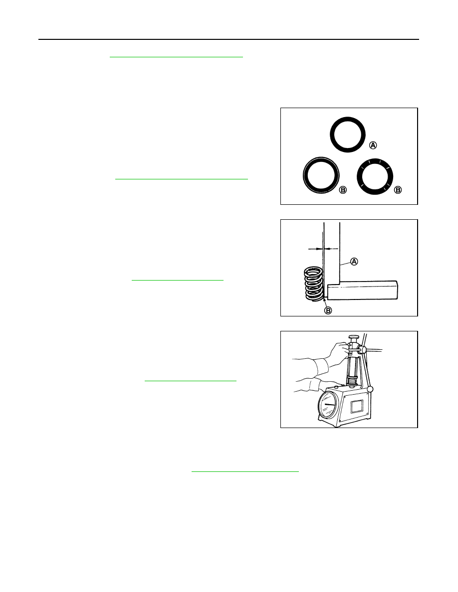
VALVE SEAT CONTACT
• After confirming that the dimensions of valve guides and valves are within the specifications, perform this
procedure.
• Apply prussian blue (or white lead) onto contacting surface of valve seat to check the condition of the valve
contact on the surface.
• Check if the contact area band is continuous all around the circum-
ference.
• If not, grind to adjust valve fitting and check again. If the contacting
surface still has “NG” conditions even after the re-check, replace
valve seat. Refer to
EM-187, "Disassembly and Assembly"
.
VALVE SPRING SQUARENESS
• Set a try square (A) along the side of valve spring and rotate
spring. Measure the maximum clearance between the top of spring
and try square.
• If it exceeds the limit, replace valve spring.
VALVE SPRING DIMENSIONS AND VALVE SPRING PRESSURE LOAD
• Check valve spring pressure with valve spring seat installed at the
specified spring height.
CAUTION:
Never remove valve spring seat from valve spring.
• If the installation load or load with valve open is out of the stan-
dard, replace valve spring (with valve spring seat).
INSPECTION AFTER INSTALLATION
Inspection for Leaks
• Before starting engine, check oil/fluid levels including engine coolant and engine oil. If less than required
quantity, fill to the specified level. Refer to
MA-21, "Fluids and Lubricants"
.
• Use procedure below to check for fuel leakage.
- Turn ignition switch “ON” (with engine stopped). With fuel pressure applied to fuel piping, check for fuel leak-
age at connection points.
- Start engine. With engine speed increased, check again for fuel leakage at connection points.
• Run engine to check for unusual noise and vibration.
• Warm up engine thoroughly to make sure there is no leakage of fuel, exhaust gases, or any oil/fluids includ-
ing engine oil and engine coolant.
• Bleed air from lines and hoses of applicable lines, such as in cooling system.
• After cooling down engine, again check oil/fluid levels including engine oil and engine coolant. Refill to the
specified level, if necessary.
A
: OK
B
: NG
JPBIA0187ZZ
B
: Contact
Limit
: Refer to
PBIC3219J
Standard
: Refer to
SEM113