Nissan Qashqai (2007-2010). Manual - part 59
 

  Index      Nissan     Nissan Qashqai - service and repair manual 2007 - 2010 year


Search            copyright infringement  


Content   ..  57  58  59  60   ..


Nissan Qashqai (2007-2010). Manual - part 59


EM-184

< ON-VEHICLE REPAIR >

[MR20DE]

OIL SEAL

2.

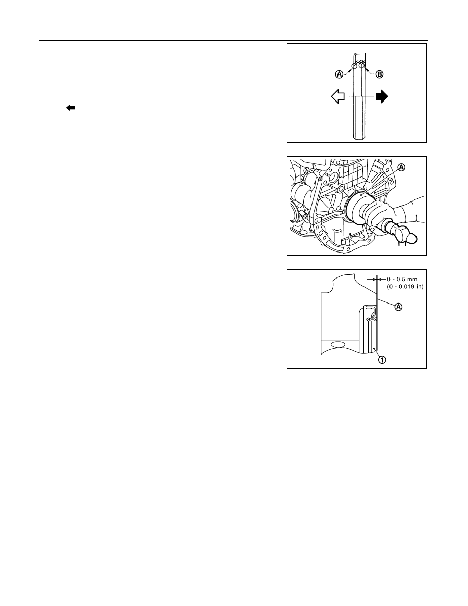
Install rear oil seal so that each seal lip is oriented as shown in
the figure.

• Press-fit rear oil seal with a suitable drift outer diameter 113

mm (4.45 in) and inner diameter 90 mm (3.54 in) (A).

CAUTION:

• Be careful not to damage crankshaft and cylinder block.
• Press-fit oil seal straight to avoid causing burrs or tilt-

ing.

• Never touch grease applied onto oil seal lip.

• Press in rear oil seal (1) to the position as shown in the figure.

3.

Install in the reverse order of removal, for the rest of parts.

A

: Dust seal lip

B

:  Oil  seal  lip

: Engine outside

: Engine inside

PBIC3485J

PBIC3951E

A

: Rear end surface of cylinder block

PBIC3761E

CYLINDER HEAD

EM-185

< ON-VEHICLE REPAIR >

[MR20DE]

C

D

E

F

G

H

I

J

K

L

M

A

EM

N

P

O

CYLINDER HEAD

Exploded View

INFOID:0000000000893956

REMOVAL

DISSASEMBLY

1.

Cylinder head assembly

2.

Cylinder head bolt

3.

Cylinder head gasket

A.

Refer to 

EM-186

Refer to 

GI-4, "Components"

 for symbols in the figure.

PBIC3542J

PBIC3543J

EM-186

< ON-VEHICLE REPAIR >

[MR20DE]

CYLINDER HEAD

Removal and Installation

INFOID:0000000000893957

REMOVAL

1.

Release fuel pressure. Refer to 

EC-978, "Inspection"

.

2.

Drain engine coolant and engine oil. Refer to 

CO-30, "Draining"

 and 

LU-15, "Draining"

.

3.

Remove the following components and related parts.
• Exhaust manifold: Refer to 

EM-149, "Exploded View"

.

• Intake manifold: Refer to 

EM-146, "Exploded View"

.

• Fuel tube and fuel injector assembly: Refer to 

EM-155, "Exploded View"

.

• Water outlet: Refer to 

CO-44, "Exploded View"

.

• Rocker cover: Refer to 

EM-160, "Exploded View"

.

• Front cover, timing chain: Refer to 

EM-162, "Exploded View"

.

• Camshaft: Refer to 

EM-173, "Exploded View"

.

4.

Remove cylinder head.
• Loosen mounting bolts in reverse order as shown in the figure. 

• Using TORX socket (size E18), loosen cylinder head bolts.

5.

Remove cylinder head gasket.

INSTALLATION

1.

Install cylinder head gasket.

2.

Install cylinder head, and tighten cylinder head bolts in numeri-
cal order as shown in figure with the following procedure.

CAUTION:

If cylinder head bolts are re-used, check their outer diame-
ters before installation. Refer to 

EM-191, "Inspection"

.

a.

Apply new engine oil to threads and seating surface of mounting
bolts.

b.

Tighten all bolts.

1.

Valve collet

2.

Valve spring retainer

3.

Valve spring (EXH)                                     
(with valve spring seat)

4.

Valve oil seal

5.

Valve guide (EXH)

6.

Valve seat (EXH)

7.

Valve (EXH)

8.

Valve (INT)

9.

Valve seat (INT)

10. Cylinder head

11. Valve guide (INT)

12. Spark plug

13.

Valve spring (INT)
(with valve spring seat)

A.

Refer to 

EM-187

B.

Refer to 

EM-187

Refer to 

GI-4, "Components"

 for symbols shown in the figure.

: Engine front

PBIC3206J

: Engine front

: 40.0 N·m (4.1 kg-m, 30 ft-lb)

PBIC3206J

CYLINDER HEAD

EM-187

< ON-VEHICLE REPAIR >

[MR20DE]

C

D

E

F

G

H

I

J

K

L

M

A

EM

N

P

O

c.

Turn all bolts 100 degrees clockwise (angle tightening).

CAUTION:

Check and confirm the tightening angle by using an angle
wrench [SST: KV10112100] (A) or protractor. Never judge by
visual inspection without the tool.

d.

Completely loosen.

CAUTION:

In this step, loosen bolts in reverse order that indicated in
the figure.

e.

Tighten all bolts.

f.

Turn all bolts 100 degrees clockwise (angle tightening).

g.

Turn all bolts 100 degrees clockwise again (angle tightening).

3.

Install in the reverse order of removal, for the rest of parts. 

Disassembly and Assembly

INFOID:0000000000893967

Disassembly

1.

Remove spark plug with spark plug wrench (commercial service tool).

2.

Remove valve lifter.
• Identify installation positions, and store them without mixing them up.

3.

Remove valve collet. 
• Compress valve spring with valve spring compressor, attach-

ment and adapter [SST: KV10116200] (A). Remove valve col-
let with a magnet hand.

CAUTION:

Be careful not to damage valve lifter holes.

4.

Remove valve spring retainer and valve spring (with valve spring seat).

CAUTION:

Never remove valve spring seat from valve spring.

5.

Push valve stem to combustion chamber side, and remove valve. 
• Identify installation positions, and store them without mixing them up.

6.

Remove valve oil seal with a valve oil seal puller [SST:
KV10107902] (A).

7.

When valve seat must be replaced.

: 0 N·m (0 kg-m, 0 ft-lb)

: 40.0 N·m (4.1 kg-m, 30 ft-lb)

PBIC3208J

PBIC3209J

PBIC3210J


Content   ..  57  58  59  60   ..