Nissan Qashqai (2007-2010). Manual - part 48
EM-140
< ON-VEHICLE MAINTENANCE >
[MR20DE]
CAMSHAFT VALVE CLEARANCE
c.
Set No.4 cylinder at TDC of its compression stroke.
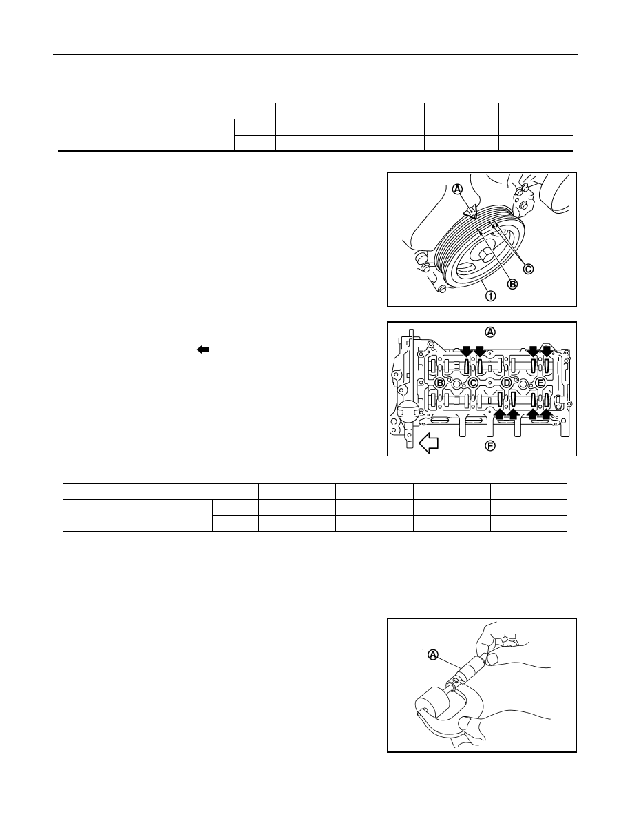
• Rotate crankshaft pulley (1) one revolution (360 degrees) and
align TDC mark (no paint) (B) to timing indicator (A) on front
cover.
• By referring to the figure, measure the valve clearance at loca-
tions marked “
×
” as shown in the table below [locations indi-
cated with black arrow (
) in the figure] with a feeler gauge.
3.
If out of standard, perform adjustment. Refer to “ADJUSTMENT”.
ADJUSTMENT
• Perform adjustment depending on selected head thickness of valve lifter.
1.
Remove camshaft. Refer to
2.
Remove valve lifters at the locations that are out of the standard.
3.
Measure the center thickness of the removed valve lifters with a
micrometer (A).
4.
Use the equation below to calculate valve lifter thickness for replacement.
F
: Intake side
: Engine front
Measuring position
No. 1 CYL.
No. 2 CYL.
No. 3 CYL.
No. 4 CYL.
No. 1 cylinder at compression TDC
EXH
×
×
INT
×
×
C : White paint mark (Not use for service)
PBIC3960E
A
: Exhaust side
B
: No.1 cylinder
C
: No.2 cylinder
D
: No.3 cylinder
E
: No.4 cylinder
F
: Intake side
: Engine front
Measuring position
No. 1 CYL.
No. 2 CYL.
No. 3 CYL.
No. 4 CYL.
No. 4 cylinder at compression TDC
EXH
×
×
INT
×
×
PBIC3194J
PBIC3195J