Nissan Qashqai (2007-2010). Manual - part 33
EM-80
< ON-VEHICLE REPAIR >
[HR16DE]
CYLINDER HEAD
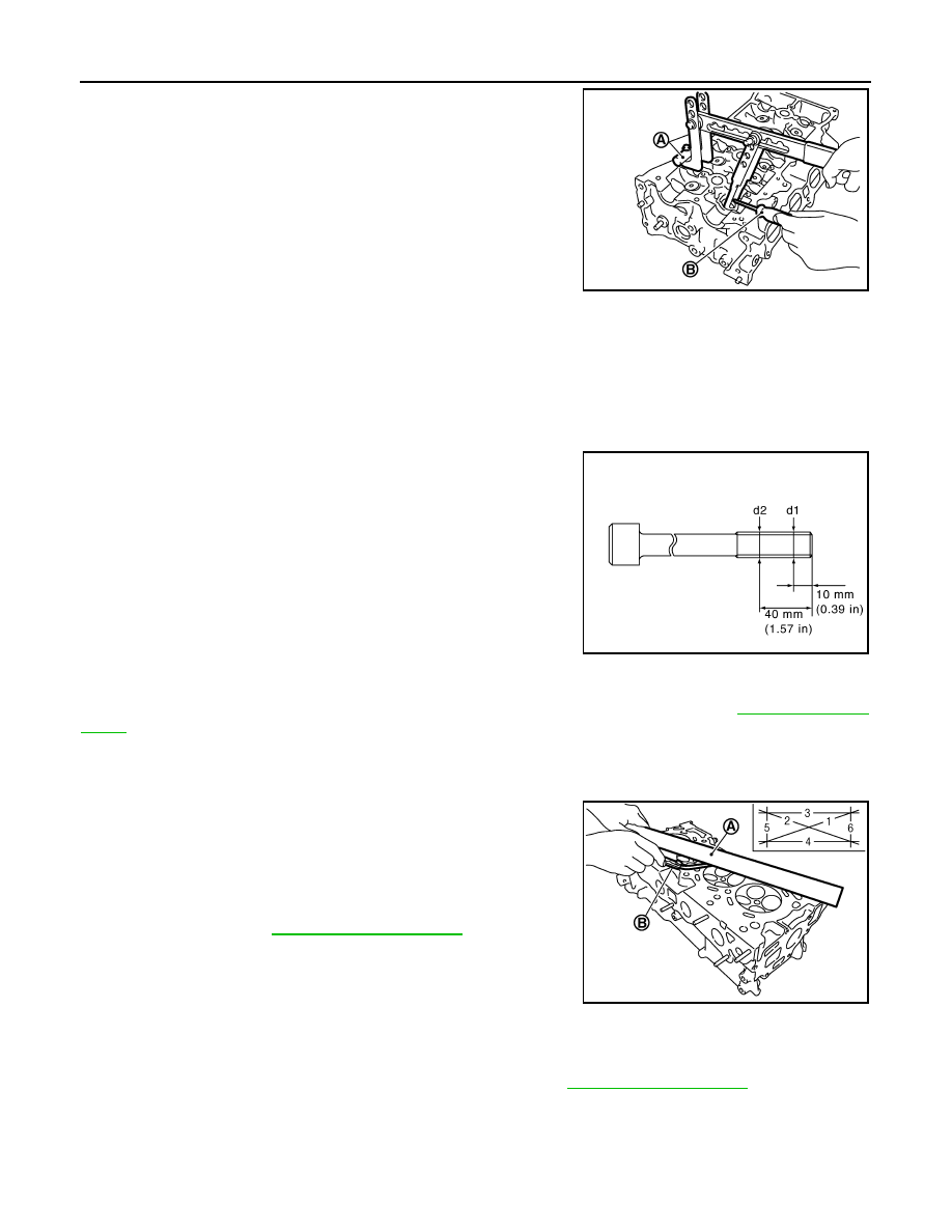
• Compress valve spring with the valve spring compressor, the
attachment and the adapter [SST: KV10116200] (A). Install
valve collet with a magnet hand (B).
CAUTION:
Be careful not to damage valve lifter holes.
• Tap valve stem edge lightly with a plastic hammer after instal-
lation to check its installed condition.
9.
Install valve lifter.
10. Install spark plug with a spark plug wrench (commercial service tool).
Inspection
INFOID:0000000000943692
INSPECTION AFTER REMOVAL
Cylinder Head Bolts Outer Diameter
• Cylinder head bolts are tightened by plastic zone tightening
method. Whenever the size difference between “d1” and “d2”
exceeds the limit, replace them with a new one.
• If reduction of outer diameter appears in a position other than “d2”,
use it as “d2” point.
Cylinder Head Distortion
NOTE:
When performing this inspection, cylinder block distortion should be also checking. Refer to
.
1.
Wipe off engine oil and remove water scale (like deposit), gasket, sealant, carbon, etc. with a scraper.
CAUTION:
Never allow gasket debris to enter passages for engine oil or engine coolant.
2.
At each of several locations on bottom surface of cylinder head,
measure the distortion in six directions.
• If it exceeds the limit, replace cylinder head.
INSPECTION AFTER DISASSEMBLY
Valve Dimensions
• Check the dimensions of each valve. For the dimensions, refer to
• If dimensions are out of the standard, replace valve and check valve seat contact. Refer to “VALVE SEAT
CONTACT”.
Valve Guide Clearance
Valve Stem Diameter
PBIC3727E
Limit (“d1”–“d2”): 0.15 mm (0.0059 in)
PBIC3717E
A
: Straightedge
B
: Feeler gauge
Limit
: Refer to
PBIC3207J