Nissan Qashqai (2007-2010). Manual - part 21
 

  Index      Nissan     Nissan Qashqai - service and repair manual 2007 - 2010 year


Search            copyright infringement  


Content   ..  19  20  21  22   ..


Nissan Qashqai (2007-2010). Manual - part 21


EM-32

< ON-VEHICLE REPAIR >

[HR16DE]

EXHAUST MANIFOLD

EXHAUST MANIFOLD

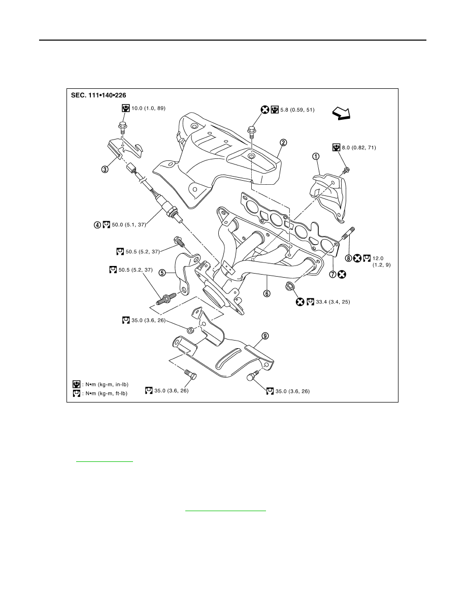
Exploded View

INFOID:0000000000893847

Removal and Installation

INFOID:0000000000894021

REMOVAL

1.

Remove exhaust front tube. Refer to 

EX-5, "Exploded View"

.

2.

Remove the harness bracket of heated oxygen sensor 1 from the cylinder head.

3.

Remove exhaust manifold cover.

4.

Remove the heated oxygen sensor 1.

1.

Exhaust manifold cover

2.

Exhaust manifold cover

3.

Harness bracket

4.

Heated oxygen sensor 1

5.

Exhaust manifold stay

6.

Exhaust manifold

7.

Gasket

8.

Stud bolt

9.

Heat insulator

: Engine front

Refer to 

GI-4, "Components"

 for symbols in the figure.

PBIC4750E

EXHAUST MANIFOLD

EM-33

< ON-VEHICLE REPAIR >

[HR16DE]

C

D

E

F

G

H

I

J

K

L

M

A

EM

N

P

O

• Using heated oxygen sensor wrench [SST: KV10117100] (A),

remove heated oxygen sensor 1.

CAUTION:

Handle heated oxygen sensor 1 carefully and avoid
impacts.
NOTE:
The exhaust manifold can be removed and installed without
removing the heated oxygen sensor 1 (Disassembly of harness
connector is necessary).

5.

Remove exhaust manifold side mounting bolt of exhaust manifold stay.

6.

Remove exhaust manifold.
• Loosen nuts in the reverse of the order shown in the figure.

7.

Remove gasket.

CAUTION:

Cover engine openings to avoid entry of foreign materials.

8.

Remove exhaust manifold cover from back of exhaust manifold.

INSTALLATION

Note the following, and install in the reverse order of removal.

Exhaust Manifold

1.

Tighten nuts in numerical order shown in the figure.

2.

Tighten to the specified torque again.

Inspection

INFOID:0000000000893849

INSPECTION AFTER REMOVAL

Mounting Surface Distortion

PBIC3654E

: Engine front

PBIC3774E

: Engine front

PBIC3774E

EM-34

< ON-VEHICLE REPAIR >

[HR16DE]

EXHAUST MANIFOLD

• Using a straightedge (B) and feeler gauge (A), check distortion of

exhaust manifold mounting surface.

• Replace exhaust manifold if outside the limit.

Limit:

Refer to 

EM-116, "Exhaust Manifold"

.

PBIC3530J

FUEL INJECTOR AND FUEL TUBE

EM-35

< ON-VEHICLE REPAIR >

[HR16DE]

C

D

E

F

G

H

I

J

K

L

M

A

EM

N

P

O

FUEL INJECTOR AND FUEL TUBE

Exploded View

INFOID:0000000000893850

CAUTION:

Never remove or disassemble parts unless instructed as shown in the figure.

Removal and Installation

INFOID:0000000000894022

WARNING:

• Put a “CAUTION: FLAMMABLE” sign in the workshop.
• Be sure to work in a well ventilated area and furnish workshop with a CO

2

  fire extinguisher. 

• Never smoke while servicing fuel system. Keep open flames and sparks away from the work area.

REMOVAL

1.

Release the fuel pressure. Refer to 

EC-357, "Inspection"

.

2.

Remove intake manifold. Refer to 

EM-29, "Exploded View"

.

1.

Quick connector cap

2.

Fuel feed hose

3.

Fuel tube

4.

Fuel tube protector

5.

O-ring (black)

6.

Clip

7.

Fuel injector

8.

O-ring (green)

Refer to 

GI-4, "Components"

 for symbols in the figure.

PBIC3663E


Content   ..  19  20  21  22   ..