Mitsubishi ASX (2018 year). Manual - part 7
 

  Index      Mitsubishi     Mitsubishi ASX - service manual 2018 year in english


Search            


Content   ..  5  6  7  8   ..


Mitsubishi ASX (2018 year). Manual - part 7


WARNING

l

Do not attach accessories to, or put them
in front of, the windscreen. These objects
could  restrict  the  airbag  inflation,  or
strike  and  injure  an  occupant  if  the  air-
bags inflate.

l

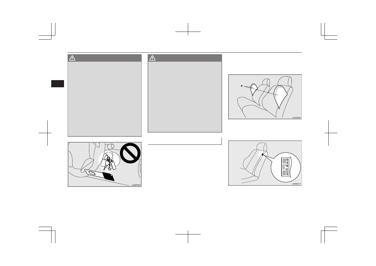
Do  not  attach  additional  keys  or  accesso-
ries  (hard,  pointed  or  heavy  objects)  to
the  ignition  key.  Such  objects  could  pre-
vent the driver’s knee airbag from inflat-
ing  normally  or  could  be  propelled  and
cause serious injury if the airbag inflates.

l

Do  not  attach  accessories  to  the  lower
portion  of  the  driver’s  side  instrument
panel.  Such  objects  could  prevent  the
driver’s  knee  airbag  from  inflating  nor-
mally or could be propelled and cause se-
rious injury if the airbag inflates.

WARNING

l

Do not put packages, pets or other objects
between  the  airbags  and  the  driver  or
front  passenger.  It  could  affect  airbag
performance, or could cause injury when
the airbag inflates.

l

Right  after  the  airbag  inflation,  several
airbag system components will be hot. Do
not  touch  these  components.  There  is  a
danger of being burnt.

l

The airbag system is designed to work on-
ly  once.  Once  the  airbags  have  deployed,
they  will  not  work  again.  They  must
promptly be replaced, and we recommend
you  to  have  the  entire  airbag  system  in-
spected  by  a  MITSUBISHI  MOTORS
Authorized Service Point.

Side airbag system*

E00407600303

The  side  airbags  (A)  are  contained  in  the
driver and front passenger seatbacks.

The side airbag is designed to inflate only on
the side of the vehicle that is impacted, even
with no passenger in the front seat.

The label shown here is attached to the seat-
backs with a side airbag.

Supplemental restraint system (SRS) - airbag

4-32

OGAE18E1

Seat and seat belts

4

Curtain airbag system*

E00409100559

The curtain airbags are contained in the front
pillars and roof side rail. The curtain airbag is
designed to inflate only on the side of the ve-
hicle  that  is  impacted,  even  with  no  passen-
ger in the front seat or rear seat.

Deployment of side airbags and

curtain airbags

E00407701415

The  side  airbags  and  curtain

airbags  ARE  DESIGNED  TO

DEPLOY when…

The  side  airbags  and  curtain  airbags  are  de-
signed  to  deploy  when  the  vehicle  suffers  a
moderate-to-severe side impact to the middle
of the passenger compartment.

The typical condition is shown in the illustra-
tion.

The  seat  belts  in  your  vehicle  are  your  pri-
mary means of protection in a collision. The
SRS side airbags and curtain airbags are de-
signed  to  provide  additional  protection.
Therefore,  for  your  safety  and  the  safety  of
all  occupants,  be  sure  to  always  properly
wear your seat belts.

The  side  airbags  and  curtain

airbags  MAY  NOT  DEPLOY

when…

With certain types of side collisions, the ve-
hicle’s  body  structure  is  designed  to  absorb
the shock to help protect the occupants from
harm. (The vehicle body’s side area may de-
form  significantly  as  it  absorbs  the  impact.)
Under  such  circumstances,  the  side  airbags
and curtain airbags may not deploy irrespec-
tive of the deformation and damage to the ve-
hicle  body.  Also,  depending  on  the  location
of the impact, the side airbags and curtain air-
bags may not deploy simultaneously.
Examples  of  some  typical  conditions  are
shown in the illustration.

1- Side  impacts  in  an  area  away  from  the

passenger compartment

2- Motorcycle  or  other  similar  small  vehi-

cle collides with the side of vehicle

Supplemental restraint system (SRS) - airbag

4-33

OGAE18E1

Seat and seat belts

4

3- Collision with a utility pole, tree or other

narrow object

4- Oblique side impacts
5- Vehicle rolls onto its side or roof

Because  the  side  airbags  and  curtain  airbags
do  not  protect  the  occupant  in  all  types  of
side  collisions,  be  sure  to  always  properly
wear your seat belts.

The  side  airbags  and  curtain

airbags  ARE  NOT  DESIGNED

TO DEPLOY when…

The  side  airbags  and  curtain  airbags  are  not
designed  to  deploy  in  conditions  where  they
cannot  usually  provide  protection  to  the  oc-
cupant.  Typical  conditions  are  shown  in  the
illustration.

1- Head-on collisions
2- Rear end collisions

Because  the  side  airbags  and  curtain  airbags
do  not  protect  the  occupant  in  all  types  of
collisions,  be  sure  to  always  properly  wear
your seat belts.

WARNING

l

The  side  airbags  and  curtain  airbags  are
designed  to  supplement  the  driver  and
passenger  seat  belts  in  certain  side  im-
pacts.  Seat  belts  should  always  be  worn
properly,  and  the  driver  and  passenger
should  sit  well  back  and  upright  without
leaning against the window or door.

l

The  side  airbags  and  curtain  airbags  in-
flate with great force. The driver and pas-
senger  should  not  put  their  arms  out  the
window,  and  should  not  lean  against  the
door, in order to reduce risk of serious or
possible  fatal  injury  from  the  deploying
side airbags and curtain airbags.

Supplemental restraint system (SRS) - airbag

4-34

OGAE18E1

Seat and seat belts

4

WARNING

l

Do  not  allow  any  rear  seat  occupant  to
hold onto the seatback of either front seat,
in order to reduce risk of injury from the
deploying  side  airbags.  Special  care
should be taken with children.

l

Do not place any objects near or in front
of  the  seatback  of  either  front  seat.  They
could interfere with proper side airbag in-
flation,  and  also  could  cause  injury  if
thrown free by side airbag deployment.

l

Do not place stickers, labels or additional
trim  on  the  seatback  of  either  front  seat.
They could interfere with proper side air-
bag inflation.

l

Do  not  install  seat  covers  on  seats  with
side  airbags.  Do  not  re-cover  seats  that
have  side  airbags.  This  could  interfere
with proper side airbag inflation.

l

Do  not  attach  a  microphone  (A)  or  any
other  device  or  object  around  the  part
where  the  curtain  airbags  (B)  activate
such as on the windscreen, side door glass,
front and rear pillars and roof side or as-
sist  grips.  When  the  curtain  airbags  in-
flate,  the  microphone  or  other  device  or
object  will  be  hurled  with  great  force  or
the  curtain  airbags  may  not  activate  cor-
rectly, resulting in death or serious injury.

WARNING

l

Do not put a hanger or any heavy or poin-
ted object on the coat hook. If the curtain
airbag was activated, any such item could
be  propelled  away  with  great  force  and
could prevent the curtain airbag from in-
flating correctly. Hang clothes directly on
the  coat  hook  (without  using  a  hanger).
Make  sure  there  are  no  heavy  or  sharp
objects  in  the  pockets  of  clothes  that  you
hang on the coat hook.

l

Never  install  a  rearward  facing  child  re-
straint in the front passenger seat. A for-
ward facing child restraint should be used
in  the  rear  seat  whenever  possible.  If  a
forward  facing  child  restraint  must  be
used  in  the  front  passenger  seat,  adjust
the  seat  to  the  most  rearward  position,
and ensure that the child stays in the child
restraint and away from the door.

WARNING

l

Do  not  allow  a  child  to  lean  against  or
close to the front door even if the child is
seated in a child restraint system.
The child’s head should also not be leaned
against  or  be  close  to  the  area  where  the
side airbags and curtain airbags are loca-
ted. It is dangerous if the side airbags and
curtain airbags inflate.
Failure  to  follow  all  of  these  instructions
could lead to serious or fatal injury to the
child.

l

We  recommend  work  around  and  on  the
side airbags and curtain airbags system to
be  done  by  a  MITSUBISHI  MOTORS
Authorized Service Point.

Supplemental restraint system (SRS) - airbag

4-35

OGAE18E1

Seat and seat belts

4

SRS warning lamp/display

E00407802790

Warning lamp

Warning display type 1

Warning display type 2

 
The system checks itself every time the igni-
tion switch is turned to the “ON” position or
the  operation  mode  is  put  in  ON.  The  SRS
warning  lamp  will  come  on  for  several  sec-
onds  and  then  go  out.  This  is  normal  and
means the system is working properly.

If there is a problem involving one or more of
the  SRS  components,  the  warning  lamp  will
come  on  and  stay  on.  At  the  same  time,  the
warning  display  will  appear  on  the  informa-
tion screen in the multi-information display.
The  SRS  warning  lamp/display  is  shared  by
the SRS airbag and the seat belt pretensioner
system.

WARNING

l

If  any  of  the  following  conditions  occur,
there may be a problem with the SRS air-
bags  and/or  seat  belt  pretensioners,  and
they may not function properly in a colli-
sion  or  may  suddenly  activate  without  a
collision:

Even  when  the  ignition  switch  or  the
operation  mode  is  in  ON,  the  SRS
warning  lamp  does  not  come  on  or  it
remains on.

The  SRS  warning  lamp  and/or  the
warning  display  comes  on  while  driv-
ing.

The SRS airbags and seat belt pretension-
ers are designed to help reduce the risk of
serious  injury  or  death  in  certain  colli-
sions. If either of the above conditions oc-
curs,  immediately  have  your  vehicle
checked  by  a  MITSUBISHI  MOTORS
Authorized Service Point.

SRS servicing

E00407901521

WARNING

l

We  recommend  any  maintenance  per-
formed on or near the components of the
SRS  to  be  performed  by  a  MITSUBISHI
MOTORS Authorized Service Point.
Improper  work  on  the  SRS  components
or  wiring  could  result  in  inadvertent  de-
ployment  of  the  airbags,  or  could  render
the  SRS  inoperative;  either  situation
could result in serious injury.

l

Do  not  modify  your  steering  wheel,  seat
belt  retractor  or  any  other  SRS  compo-
nents.  For  example,  replacement  of  the
steering  wheel,  or  modifications  to  the
front  bumper  or  body  structure  can  ad-
versely  affect  SRS  performance  and  lead
to possible injury.

l

If your vehicle has sustained any damage,
we  recommend  you  to  have  the  SRS  in-
spected  to  ensure  it  is  in  proper  working
order.

Supplemental restraint system (SRS) - airbag

4-36

OGAE18E1

Seat and seat belts

4

WARNING

l

On  vehicles  with  the  side  airbags,  do  not
modify your front seats, centre pillar and
centre console.
It  can  adversely  affect  SRS  performance
and lead to possible injury.
If  you  found  any  tear,  scratch,  crack  or
damage  to  the  seat  fabric  near  the  side
airbag,  the  portion  of  the  front  and  rear
pillars and roof side rail, you should have
the  SRS  inspected  by  a  MITSUBISHI
MOTORS Authorized Service Point.

NOTE

l

When you transfer ownership of the vehicle
to  some  other  person,  we  urge  you  to  alert
the  new  owner  that  it  is  equipped  with  the
SRS and refer the new owner to the applica-
ble section in this owner’s manual.

l

If your vehicle has to be scrapped, do this in
line  with  local  legislation  and  contact  a
MITSUBISHI  MOTORS  Authorized  Serv-
ice Point to safely dismantle the airbag sys-
tem.

Supplemental restraint system (SRS) - airbag

4-37

OGAE18E1

Seat and seat belts

4


OGAE18E1

Instruments

E00500101147

1- Tachometer 

® p. 5-02

2- Multi-information display 

® p. 5-03

Information screen display list

® p. 5-27

3- Speedometer (km or mph + km/h)
4- Daytime dipper button (meter illumina-

tion control) 

® p. 5-02

Tachometer

E00500301123

The  tachometer  indicates  the  engine  speed
(r/min).  The  tachometer  helps  you  to  obtain
more economical driving and also warns you
of excessive engine speeds (Red zone).

CAUTION

l

When driving, watch the tachometer to make
sure  that  the  engine  speed  indication  does
not  rise  into  the  red  zone  (excessive  engine
rpm).

Daytime dipper button (meter

illumination control)

E00519801267

Each  time  you  press  this  button,  there  is  a
sound  and  the  brightness  of  the  instruments
changes.

NOTE

l

You can adjust to 8 different levels for when
the position lamps are illuminated and 8 for
when they are not.

l

When the lamp switch is in a position other
than the “OFF” position, the meter illumina-
tion  switches  automatically  to  the  adjusted
brightness, depending on the brightness out-
side the vehicle.

l

The  brightness  level  of  the  instruments  is
stored when the ignition switch is turned to
the “LOCK” position or the operation mode
is put in OFF.

l

If  you  press  and  hold  the  button  for  longer
than about 1 second when the position lamps
are illuminated, the brightness level changes
to the maximum level. Pressing and holding
the  button  for  longer  than  about  1  second
again returns the brightness level to the pre-
vious level.

1- Brightness display
2- Rheostat illumination button

Instruments

5-02

OGAE18E1

Instruments and controls

5

Multi-information display

E00519902959

Always stop the vehicle in a safe place before operating.
The following information is included on the multi-information display: warnings, odometer, tripmeter, service reminder, engine coolant temper-
ature,  fuel  remaining,  outside  temperature,  selector  lever  position,  4WD  operation  status,  average  and  momentary  fuel  consumption,  driving
range, average speed and meter illumination.
It is also possible to change elements such as the language and units used on the multi-information display.

When the ignition switch or the operation 
mode is OFF

Type 1

Type 2

Type 1

Type 2

Type 1

Type 2

When the ignition switch or the operation 
mode is ON (A/T, CVT)

When the ignition switch or the operation 
mode is ON (M/T)

1-

 mark display screen (when the igni-

tion switch or the operation mode is
OFF) 

® p. 5-05

2- Information screen (when the ignition

switch or the operation mode is OFF)

® p. 5-05
Interrupt display screen (when the igni-
tion switch or the operation mode is
OFF) 

® p. 5-07

3- Door ajar warning display screen (when

the ignition switch or the operation
mode is OFF) 

® p. 5-08

4- Drive mode indicator display screen*

® p. 5-09

5-

 mark display screen (when the igni-

tion switch or the operation mode is ON)

® p. 5-09

Multi-information display

5-03

OGAE18E1

Instruments and controls

5

6- Lane Departure Warning (LDW) display

screen* 

® p. 6-68

7- Information screen (when the ignition

switch or the operation mode is ON)

® p. 5-10
Interrupt display screen (when the igni-
tion switch or the operation mode is ON)

® p. 5-14

8- Selector lever position display screen*

® p. 5-15
Gearshift indicator display screen*

® p. 6-29

9- Outside temperature display screen

® p. 5-15

10- Fuel remaining display screen

® p. 5-15

11- Engine coolant temperature display*

® p. 5-11

12- Gearshift indicator display screen*

® p. 6-23

13- Auto Stop & Go (AS&G) display

screen* 

® p. 6-19

Auto Stop & Go (AS&G) OFF display
screen* 

® p. 6-22

NOTE

l

The fuel units, temperature units, display language, and other settings can be changed.
Refer to “Changing the function settings (when the ignition switch or the operation mode is ON)” on page 5-19.

l

The display screen is different depending on whether the ignition switch or the operation mode is OFF or ON.
Refer to “Information screen (when the ignition switch or the operation mode is OFF)” on page 5-05.
Refer to “Warning display list (when the ignition switch or the operation mode is OFF)” on page 5-28.
Refer to “Information screen (when the ignition switch is turned from the “LOCK” position to the “ON” position or the operation mode is changed from
OFF to ON)” on page 5-08.
Refer to “Information screen (when the ignition switch or the operation mode is ON)” on page 5-10.
Refer to “Warning display list (when the ignition switch or the operation mode is ON)” on page 5-31.


Multi-information meter

switch

E00520000608

Each time the multi-information meter switch
is operated, a sound is emitted and the multi-
information  display  changes  between  infor-
mation such as warnings, odometer (Type 1),
tripmeter,  service  reminder,  engine  coolant
temperature (Type 1), average and momenta-
ry fuel consumption, driving range, and aver-
age speed.

Multi-information display

5-04

OGAE18E1

Instruments and controls

5

It is also possible to change elements such as
the  language  and  units  used  on  the  multi-in-
formation  display  by  operating  the  multi-in-
formation meter switch.

 mark display screen (when

the ignition switch or the oper-

ation mode is OFF)

E00520100553

If  you  press  the  multi-infor-
mation  meter  switch  and  re-
turn  from  the  warning  dis-
play  screen  to  the  previous
screen,  the    mark  is  dis-
played.

Refer  to  “To  return  to  the  screen  displayed
before the warning display” on page 5-07.
This mark is also displayed if there is another
warning  other  than  the  one  displayed.  When
the  cause  of  the  warning  display  is  elimina-
ted, the   mark goes out automatically.

NOTE

l

When the   mark is displayed, the warning
display screen can be redisplayed on the in-
formation screen.
Refer to “Information screen (when the igni-
tion  switch  or  the  operation  mode  is  OFF)”
on page 5-05.
Refer to “Information screen (when the igni-
tion  switch  or  the  operation  mode  is  ON)”
on page 5-10.

Information screen (when the

ignition switch or the operation

mode is OFF)

E00520200570

Each  time  you  lightly  press  the  multi-infor-
mation  meter  switch,  the  display  screen
switches in the following order.

Type 1

Type 2

When there is no
warning display

When there is a
warning display

When there is no
warning display

When there is a
warning display

1- Odometer (Type 1)/Tripmeter 
2- Odometer (Type 1)/Tripmeter 

Multi-information display

5-05

OGAE18E1

Instruments and controls

5

3- Service reminder
4- Redisplay of a warning display screen

Odometer/Tripmeter

E00521201516

Each  time  you  lightly  press  the  multi-infor-
mation  meter  switch,  the  display  screen
switches.
 
Odometer/Tripmeter 

  →  Odometer/Trip-

meter 

  →  Service  reminder  →  Redisplay

of  a  warning  display  screen  →  Odometer/
Tripmeter 

Odometer

The  odometer  indicates  the  distance  travel-
led.

Tripmeter

The tripmeter indicates the distance travelled
between two points.
 
Example usage of tripmeter 

 and tripmeter

It  is  possible  to  measure  two  currently
travelled  distances,  from  home  using
tripmeter 

 and from a particular point

on the way using tripmeter 

.

To reset the tripmeter
To  return  the  display  to  0,  hold  down  the
multi-information  meter  switch  for  about  2
seconds  or  more.  Only  the  currently  dis-
played value will be reset.
 
Example
If  tripmeter 

  is  displayed,  only  tripmeter

 will be reset.

Type 1

Type 2

NOTE

l

If there is no warning display, the switching
sequence  is:  Odometer/Tripmeter 

  →

Odometer/Tripmeter 

 → Service remind-

er → Odometer/Tripmeter 

.

l

Both tripmeters 

 and 

 can count up to

9999.9 km (9999.9 miles).
When  a  tripmeter  goes  past  9999.9  km
(9999.9  miles),  it  returns  to  0.0  km
(0.0 miles).

l

When disconnecting the battery terminal, the
memories  of  tripmeter  display 

  and  dis-

play 

 are erased, and their displays return

to 0.0 km (0.0 miles).

Service reminder

E00521301126

This  displays  the  distance
and  number  of  months  until
the next periodic inspection.
Refer  to  “Service  reminder”
on page 5-16.

Type 1

Type 2

Multi-information display

5-06

OGAE18E1

Instruments and controls

5

Interrupt display screen (when

the ignition switch or the oper-

ation mode is OFF)

E00520500616

When  there  is  information  to  be  announced,
such  as  lamp  reminders,  the  buzzer  sounds
and the multi-information display switches to
the  warning  display  screen.  Refer  to  the  ap-
propriate  page  and  take  the  necessary  meas-
ures.
When  the  cause  of  the  warning  display  is
eliminated, the warning display goes out au-
tomatically.
Refer to “Warning display list (when the ig-
nition switch or the operation mode is OFF)”
on page 5-28.

Type 1

Type 2

1- Information generated
2- Cause eliminated

To  return  to  the  screen  dis-

played  before  the  warning  dis-

play

Even  if  the  cause  of  the  warning  display  is
not  eliminated,  you  can  return  to  the  screen
that  was  displayed  before  the  warning  dis-
play.
If  you  press  the  multi-information  meter
switch,  the  display  screen  switches  to  the
screen that was displayed before the warning
display and the   mark (A) is displayed.

Type 1

Type 2

NOTE

l

Warning display screens with a “ ” or “ ”
mark  displayed  in  the  upper  right  of  the
screen  can  be  switched.  If  you  want  to
switch  the  display,  press  the  multi-informa-
tion meter switch as follows.
“ ”: Press lightly.
“ ”: Press for about 2 seconds or more.

Redisplay of a warning display screen
When the   mark is displayed, if you lightly
press  the  multi-information  meter  switch  a
few  times,  the  warning  display  screen  you
switched from is displayed again.
Refer to “Information screen (when the igni-
tion  switch  or  the  operation  mode  is  OFF)”
on page 5-05.

Multi-information display

5-07

OGAE18E1

Instruments and controls

5

Door ajar warning display

screen (when the ignition

switch or the operation mode is

OFF)

E00520600473

If any of the doors or the tailgate is not com-
pletely closed, this displays the open door or
tailgate.

Type 1

Type 2

1- Doors and tailgate are closed
2- Doors or tailgate are open

Information screen (when the

ignition switch is turned from

the “LOCK” position to the

“ON” position or the operation

mode is changed from OFF to

ON)

E00520702234

When  the  ignition  switch  is  turned  to  the
“ON” position or the operation mode is put in
ON,  the  display  screen  switches  in  the  fol-
lowing order.

Type 1

Type 2

1- Screen when the ignition switch or the

operation mode is OFF

2- System check screen
3- Screen when the ignition switch or the

operation mode is ON

System check screen

When  the  ignition  switch  is  turned  to  the
“ON” position or the operation mode is put in
ON, the system check screen is displayed for
about 4 seconds. If there is no fault, informa-
tion  screen  (when  the  ignition  switch  or  the
operation mode is ON) is displayed.
If there is a fault, the screen changes to warn-
ing display.
Refer to “Warning display list (when the ig-
nition switch or the operation mode is ON)”
on page 5-31.

Type 1

Type 2

NOTE

l

The  system  check  screen  display  varies  de-
pending on the customer’s equipment.

Multi-information display

5-08

OGAE18E1

Instruments and controls

5

Service reminder

When  the  time  for  periodic  inspection  ar-
rives,  the  warning  display  is  displayed  for  a
few  seconds  after  the  ignition  switch  or  the
operation mode ON screen. Refer to “Service
reminder” on page 5-16.

Type 1

Type 2

Drive mode indicator display

screen*

E00520800303

Type 1

Type 2

This displays the 4WD status.

If  you  select  “4WD  LOCK”  mode  with  the
drive  mode  selector,  “4WD  LOCK”  is  dis-
played;  if  you  select  “4WD  AUTO”  mode,
“4WD” is displayed.
Nothing is displayed when 2WD mode is se-
lected.  Refer  to  “Drive  mode-selector”  on
page 6-39.

 mark display screen (when

the ignition switch or the oper-

ation mode is ON

E00520900333

This  is  displayed  when  you
press  the  multi-information
meter  switch  and  switch  the
warning display screen.
This  mark  is  also  displayed
if  there  is  another  warning

other than the one displayed.
When  the  cause  of  the  warning  display  is
eliminated, the   mark goes out automatical-
ly.

NOTE

l

When the   mark is displayed, the warning
display screen can be redisplayed on the in-
formation screen.
Refer to “Information screen (when the igni-
tion  switch  or  the  operation  mode  is  OFF)”
on page 5-05.
Refer to “Information screen (when the igni-
tion  switch  or  the  operation  mode  is  ON)”
on page 5-10

Multi-information display

5-09

OGAE18E1

Instruments and controls

5


Content   ..  5  6  7  8   ..