Lifan 620. Service manual - part 42
 

  Index      Lifan     Lifan 620 - service and repair manual 2008 year


Search            


Content   ..  40  41  42  43   ..


Lifan 620. Service manual - part 42


The use conditions are: 

1) Speed is less than 2 km/h; 

2) Not connected to fault diagnostic instrument; 

3) Wire L (pin 7 in the internal diagnosis interface) is always grounded during diagnosis. 

Besides, restore ECU mode of ABS to normal mode (diagnosis mode before) after DTC read. 

Method: after diagnosis, disconnect wire L from ground, turn the key to off-power condition, and 

connect again. 

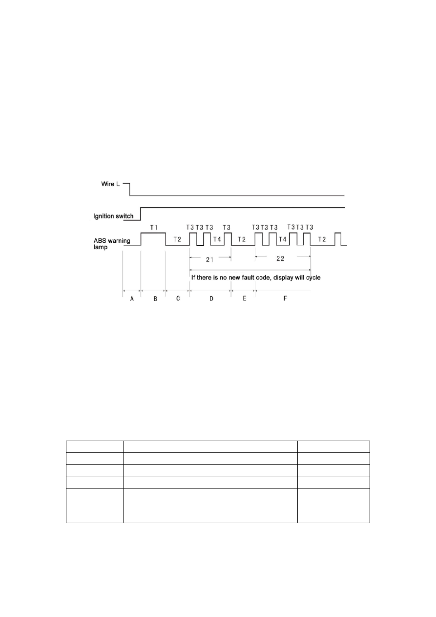
(2) Method of DTC read without fault diagnostic instrument 

Read in the following steps if meeting the conditions of DTC read without fault diagnostic 


T1 

Symbol of diagnosis start; warning lamp flickers 

3.0s 

T2 

Interval of different DTC 

3.0s 

T3 

Warning lamp flash interval in case of DTC 

0.5s 

T4 

Interval of different digital place of a DTC (the ten’s place 

is displayed before the interval and the unit’s place is 

after the interval) 

1.5s 

Take the procedure illustrated in Fig. 3-16 for example. In the display area of the first DTC, as 

warning lamp blinks twice (each on and off is T3, 0.5 second) before T4 (1.5 seconds before 

warning lamp is turned on), the first mark (ten’s place) of the 2 digital code is 2; as warning lamp 

169

blinks once after T4 (1.5 seconds after warning lamp is turned off), the second mark of the 2 digital 

code (unit’s place) is 1; as then warning lamp is turned off for 3 seconds (T2), the display of the 

first DTC is finished, and the DTC is 21. Detailed description of the fault can be found in the DTC 

Table of Section 2.4. It is the same with DTC 22. 

(3) Deletion of DTC without fault diagnostic instrument 

After DTC read and fault elimination according to DTC Table, previous DTC should be deleted 

before next DTC check. The conditions of DTC deletion are the same with that of DTC read, as 

shown in Fig. 3-17. 


symbols are the same with that above. 


Fig. 3-18 

170

4. DTC Table   

(1) DTC content is in Table 3-8. 

(2) See Table3-9, Table 3-10, Table 3-11, Table 3-12, Table 3-13, Table 3-14 and Table 3-15 for 

DTC Table. 


Table 3-8


DTC Content 

DTC 

Content 

C1 200 

Left front sensor open/short circuit 

C1 206 

Left rear sensor open/short circuit 

C1 201 

Left front sensor or gear ring disturbance 

C1 207 

Left rear sensor or gear ring disturbance

procedure 


171

Table 3-9 (continued) 


172


Content   ..  40  41  42  43   ..