Lifan 620. Service manual - part 37
 

  Index      Lifan     Lifan 620 - service and repair manual 2008 year


Search            


Content   ..  35  36  37  38   ..


Lifan 620. Service manual - part 37


Fig. 2-75 

 Dismantle the connector of the parking brake rod switch.


Fig. 2-76 

(1) Removal   
Remove the No. 2 parking brake cable components by the same way with the right side.   
1) Remove the trim strip of the instrument cluster and air conditioning control panel. 
2) Remove the two bolts of the fixed fascia console and auxiliary fascia console beneath the 
position of the air conditioning control panel. 
3) Remove and replace the bolt 3 (both left and right) 
4) Remove the floor brake cover. 
5) Open the auxiliary fascia console sundries box cover, and dismantle the two bolts at the bottom. 

149

6) Remove the No. 1 adjustment nut lead.   
7) Remove the accessories of the parking brake rod as shown in Fig. 2-76. 

 Dismantle the connector of the parking brake rod switch.


 Take off the parking brake rod after removing the 2

 bolts.   

8) Dismantle the parking brake switch components. Remove the bolts and parking brake switch 
components.  
9) Dismantle the components of the front exhaust pipe. 
10) Dismantle the No. 2 front floor heat-insulating pad. Remove the 2 bolts and take off the front 
floor hear-insulating pad.   
11) Disassemble the No. 3 parking brake cable components.   


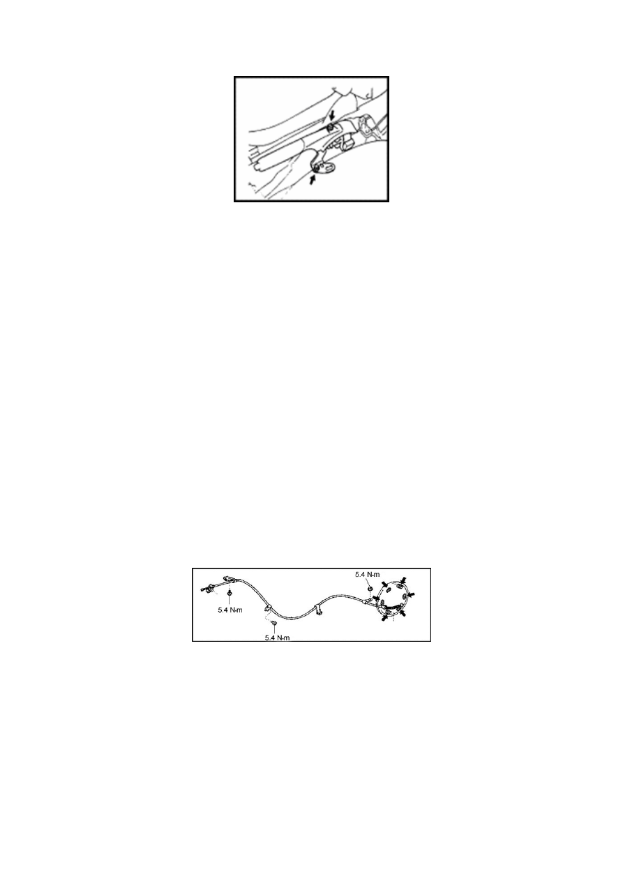
Fig. 2-78 


Connect the components of No. 3 parking brake cable to the balancer.   

 Tighten the No. 3 parking brake cable by 4 bolts. 

Tightening torque: 5.4N·m. 

2) Install the components of No. 3 parking brake cable. Tighten the components of No. 3 parking 

150


151

Section IV  Fuel System 


I. Removal and Installation   

1. Operation before removal   


Suck the fuel   

 Avoid fuel flowing to the floor 


 Remove the secondary muffler 


2. Operation after installation   

17. Snap spring under the oil filler shield                                   18. Oil filler shield  

19. Snap spring above the oil filler shield                          20. Components of oil filler cap  

21. B-type worm-driven hoop                                    22. Lower section of filler tube  

23. Filler tube lower shield   

4. Notes for fuel tank removal   
(1) Raise the vehicle by a lifter. Assistant support should be provided when supporting/raising the 
fuel tank by a jack to avoid the fuel tank turning over.   
(2) Do not attempt to repair a certain section of the rubber tube, but replace the entire tube 
instead. 

152


Content   ..  35  36  37  38   ..