Lifan 620. Service manual - part 27
 

  Index      Lifan     Lifan 620 - service and repair manual 2008 year


Search            


Content   ..  25  26  27  28   ..


Lifan 620. Service manual - part 27


III. Maintenance   

i. Wheel alignment adjustment 
1. Front wheel extroversion adjustment   
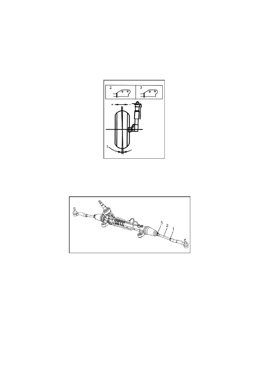
The front wheel extroversion is adjusted as shown in Fig. 2-7. Raise the vehicle, and dismantle the 
support from the vehicle. Fix the support on the bench clamp and gouge holes on the side panel. 
The extroversion can be adjusted by the bolt hole between the file support and steering knuckle.   


Details as below:   
(1) Dismantle the small boot clamp on the steering stabilizer bar. 
(2) Adjust the steering wheel to the front center position. 
(3) As shown in Fig. 2-8, release the hexagon bolt, and revolve the steering stabilizer bar for a 
proper toe-in angle. 
(4) Confirm that each steering stabilizer bar revolves for the same turns. 
(5) Tighten the locking nut. 
(6) Install the boot clamp. 

109

ii. Replacement of parts and components assembly 
1. Replacement of front brake wheel hub assembly   
(1) Disassembly of front brake wheel hub assembly   
1) Raise and properly support the vehicle and dismantle the wheel assembly. 
2) As per Fig. 2-9, disconnect the wheel speed sensor connector, and remove the sensor from the 
bracket. 


Fig. 2-11 

110

(2) Installation of front brake wheel hub assembly   
To install, reverse the removal procedure. When installing front wheel speed sensor, please 
ensure that the connector clip is well matched. 
2. Replacement of front stabilizer bar   
(1) Disassembly of front stabilizer bar. Disconnect the related connections. Lower the whole front 
sub-frame according to Fig. 2-12. 


Fig. 2-13 


(2) Installation: Install the front stabilizer, reverse the removal procedure.   
3. Replacement of steering knuckle.   

111

The steering knuckle is replaced together with the brake gear assembly according to related 
sections about brake gear.   
4. Replacement of lower arm assembly 
(1) Disassembly of the lower arm assembly   
1) Revolve the steering wheel to move the relevant front wheel to the minimum side position.   
2) According to Fig. 2-14, dismantle the cotter pin and slotted nut from the ball head bolt, and 
knock the steering knuckle to remove the ball pin of the lower arm from the steering knuckle.   


Fig. 2-15 

 
4) Check the lower arm assembly 

 Before installing nuts, shake the ball pin bolt for over 5 times as described in Fig. 2-16. 

 Use a torque wrench to rotate the nuts at a speed of a turn for each 2-4s, and record the 

112


Content   ..  25  26  27  28   ..