Lexus UX250H (2024 year). Manual in english - page 9
 

  Index      Manuals     Lexus UX250H (2024 year). Manual in english


Search            copyright infringement  


Content      ..     7      8      9      10     ..


Lexus UX250H (2024 year). Manual in english - page 9


280

5-2. Using the air conditioning system and defogger

1

Press the automatic mode switch.

2

Adjust the temperature setting.

3

To stop the operation, press the off 
switch.

If the fan speed setting or air flow 
modes are operated, the automatic 
mode indicator goes off. However, 
automatic mode for functions other 
than that operated is maintained.

Using automatic mode

Fan speed is adjusted automatically 

according to the temperature setting and 

the ambient conditions.

Therefore, the fan may stop for a while until 

warm or cool air is ready to flow immedi-

ately after the automatic mode switch is 

pressed or “AUTO” is selected.
Cool air may blow around the upper body 

even when the heater is on due to sunlight.

To turn on the “Sync” mode, select 
“Sync” on the air conditioning control 
screen.

The driver’s side temperature control 
switches can be used to adjust the tem-
perature for the driver’s and passenger’s 
side. To enter individual mode, operate the 

passenger’s side temperature control 
switches or select “Sync” again. When the 
“Sync” mode is on, the indicator illuminates 
on display.

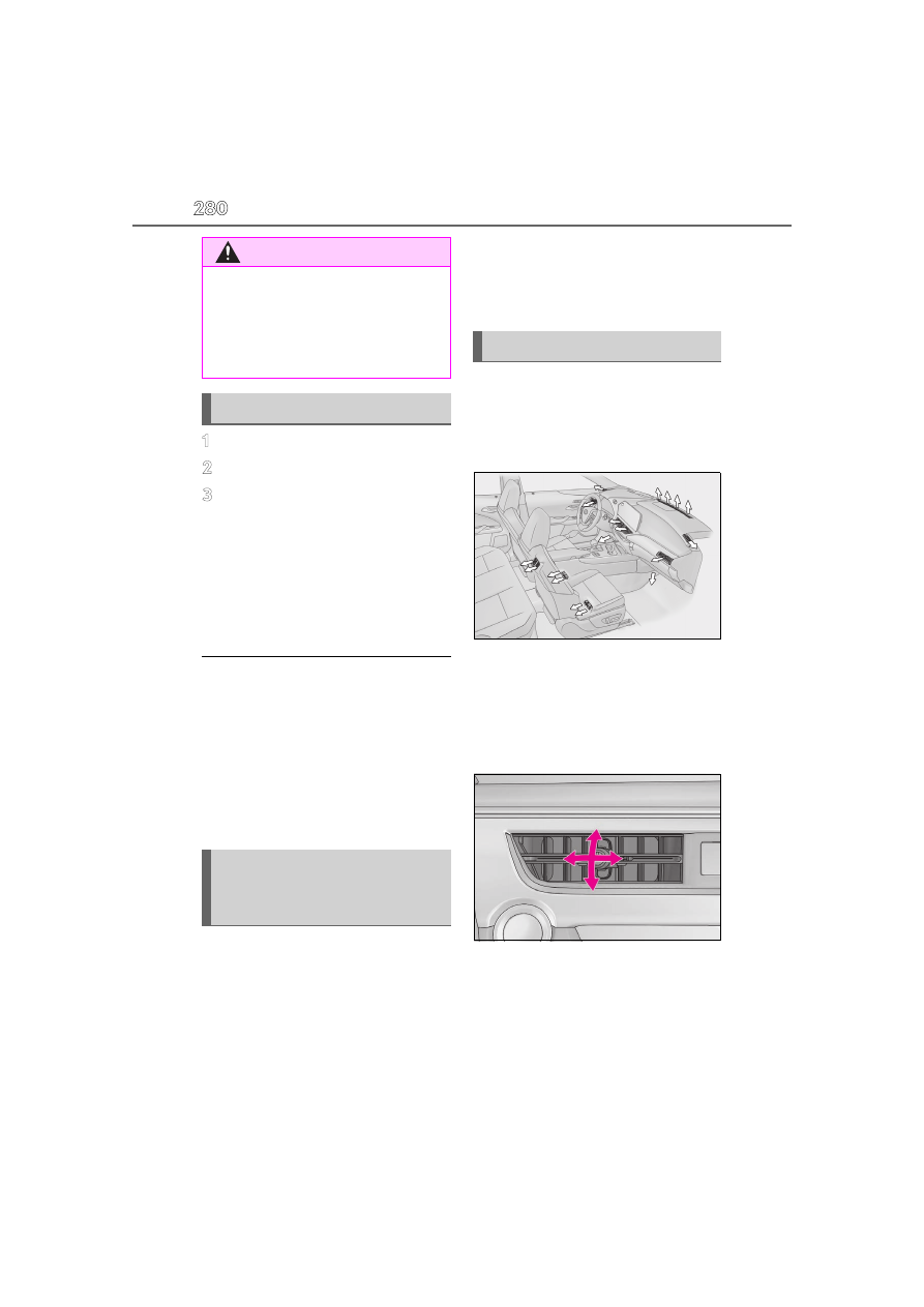
Location of air outlets

The air outlets and air volume changes 
according to the selected air flow 
mode.

Adjusting the position of and open-
ing and closing the air outlets

Front

Direct air flow to the left or right, up or 
down

Turn the knob to open or close the vent

WARNING

To prevent burns (vehicles with wind-

shield wiper de-icer)

Do not touch the glass at lower part of 

the windshield or to the side of the front 

pillars when the windshield wiper de-icer 

is on.

Using automatic mode

Adjusting the temperature for 
driver and front passenger seats 
simultaneously (“Sync” mode)

Air outlet layout and operations

281

5-2. Using the air conditioning system and defogger

5

In

te

rio

r f

ea

tu

re

s

1

Open the outlet

2

Close the outlet

Rear

1

Direct air flow to the left or right, up 
or down

2

Turn the knob to open or close the 
vent

This function automatically controls the 
air conditioning airflow so that priority 
is given to the front seats. Unnecessary 
air conditioning is suppressed, contrib-
uting to increased fuel efficiency.
Front seat concentrated airflow mode 
operates in the following situations.

No passengers are detected in the 
rear seats

The windshield defogger is not 
operating

While operating, the indicator on the air 
conditioning control screen illuminates.

Manually turning front seat con-
centrated airflow mode on/off

In front seat concentrated airflow 
mode, directing airflow to the front 
seats only and to all seats can be 
switched via switch operation. When 
the mode has been switched manually, 
automatic airflow control stops operat-
ing.

Select 

 on the air conditioning 

control screen (

P.278) and switch 

the airflow.

Indicator illuminated: Airflow to the 
front seats only

Indicator off: Airflow to all the seats

Operation of automatic airflow control

In order to maintain a comfortable inte-

rior, airflow may be directed to seats 

without passengers immediately after the 

hybrid system is started and at other 

times depending on the outside tempera-

WARNING

To prevent the windshield defogger 

from operating improperly

Do not place anything on the instrument 

panel which may cover the air outlets. 

Otherwise, air flow may be obstructed, 

preventing the windshield defoggers 

from defogging.

Front seat concentrated airflow 
mode (S-FLOW)

282

5-2. Using the air conditioning system and defogger

ture.

After the hybrid system is started, if pas-

sengers move around inside or enter/exit 

the vehicle, the system cannot accurately 

detect the presence of passengers and 

automatic airflow control will not oper-

ate.

Operation of manual airflow control

Even if the function is manually switched to 

directing airflow to only the front seats, 

when a rear seat is occupied, it may auto-

matically direct airflow to all seats.

To return to automatic airflow control

1

With the indicator off, turn the power 

switch off.

2

After 60 minutes or more elapse, turn 

the power switch to ON.

*

: If equipped

Heated steering wheel

*

/seat 

heaters

*

/seat ventilators

*

Heated steering wheel

Warms up the grip of the steering 
wheel

Seat heaters

Warm up the seat upholstery

Seat ventilators

Maintain good airflow on the seat 
upholstery by sucking air into the 
seats

WARNING

To prevent minor burn injuries

Care should be taken if anyone in the fol-

lowing categories comes in contact with 

the steering wheel or seats when the 

heater is on:

Babies, small children, the elderly, the 

sick and the physically challenged

Persons with sensitive skin

Persons who are fatigued

Persons who have taken alcohol or 

drugs that induce sleep (sleeping 

drugs, cold remedies, etc.)

NOTICE

To prevent damage to the seat heat-

ers and seat ventilators

Do not put heavy objects that have an 

uneven surface on the seat and do not 

stick sharp objects (needles, nails, etc.) 

into the seat.

To prevent 12-volt battery discharge

Do not use the functions when the hybrid 

system is off.

283

5-2. Using the air conditioning system and defogger

5

Interio

r fe

atures

Turns the heated steering wheel on/off

Each time the switch is pressed, the opera-
tion condition changes as follows.
AUTO (lit) 

 Hi (2 segments lit) 

 Lo (1 

segment lit) 

 Off

The AUTO indicator 

 and/or level indi-

cator 

 illuminates during operation.

The heated steering wheel can be used 

when

The power switch is in ON.

Customization

Steering wheel heating preference in auto-

matic mode can be changed. (Customiz-

able features: 

P.436)

Seat heaters

Turns the seat heaters on/off

Each time the switch is pressed, the opera-
tion condition changes as follows.
AUTO (lit) 

 Hi (3 segments lit) 

 Mid 

(2 segments lit) 

 Lo (1 segment lit) 


Off

The AUTO indicator 

 and/or level indi-

cator 

 illuminates during operation.

Seat ventilators

Turns the seat ventilators on/off

Each time the switch is pressed, the opera-
tion condition changes as follows.
AUTO (lit) 

 Hi (3 segments lit) 

 Mid 

(2 segments lit) 

 Lo (1 segment lit) 


Off

The AUTO indicator 

 and/or level indi-

cator 

 illuminates during operation.

The seat ventilators can be used when

The power switch is in ON.

Air conditioning system-linked control 

mode

When the seat ventilator fan speed level is 

Hi, the seat ventilator fan speed becomes 

higher according to the fan speed of the air 

conditioning system.

Customization

Settings for the seat heaters and ventilators 

can be changed. (Customizable features: 

P.435)

Heated steering wheel

Seat heaters and ventilators 
(front seats)

A

B

A

B

A

B

284

5-2. Using the air conditioning system and defogger

1

Select 

 in the main menu on the 

Center Display.

2

Select “Comfort”.

Adjust the seat ventilator fan speed 
level

Each time the switch is selected, the fan 
speed level and level indicator (blue) 
change as follows:
Hi (3 segments lit) 

 Mid (2 segments lit) 

 Lo (1 segment lit) 

 Off

Adjust the seat heater temperature 
level

Each time the switch is selected, the tem-
perature level and level indicator (red) 
change as follows:
Hi (3 segments lit) 

 Mid (2 segments lit) 

 Lo (1 segment lit) 

 Off

Adjust the heated steering wheel 

temperature level

Each time the switch is selected, the tem-
perature level and level indicator (red) 
change as follows:
Hi (2 segments lit) 

 Lo (1 segment lit) 


Off

Set the automatic mode

Each of the following functions can be set 
to automatic mode.
When the automatic mode is on, the switch 
on the screen illuminates.
• Left-hand side seat heater/seat ventila-

tor

• Right-hand side seat heater/seat ventila-

tor

• Heated steering wheel

WARNING

To prevent causes of overheating and 

minor burn injuries

Observe the following precautions when 

using the seat heaters.

Do not cover the seat with a blanket or 

cushion when using the seat heater.

Do not use seat heater more than nec-

essary.

Control screen

A

B

C

D

285

5-3. Using the interior lights

5

Interio

r fe

atures

5-3.Using the interior lights

Personal lights (

P.287)

Front interior light (

P.286)

Rear interior light (

P.286)

Footwell lights

*1, 2

Outside door handle lights (if equipped)

Door courtesy lights

Auxiliary tray lights (if equipped)

*2

*1

: When the power switch is in ON, the footwell lights will turn on.

However, if the instrument panel light control switch is turned to minimum, the footwell 
lights will turn off. (

P.82, 88)

*2

: These lights turn on when a door is unlocked. When the shift lever is in a position other 

than P, the brightness of these lights will reduce intensity.

Personal lights/interior lights automatic on/off

Illuminated entry system: The lights auto-

matically turn on/off according to power 

switch mode, the presence of the elec-

tronic key, whether the doors are 

locked/unlocked, and whether the doors 

are opened/closed.

Interior lights list

Location of the interior lights

A
B
C
D

E
F

G

286

5-3. Using the interior lights

If the interior lights remain on when the 

power switch is turned off, the lights will 

go off automatically after 20 minutes.

When front interior light and personal 

lights do not respond as normal

When water, dirt, etc., have adhered to 

the lens surface

When operated with a wet hand

When wearing gloves, etc.

The interior lights will turn on automati-

cally when

If any of the SRS airbags deploy (inflate) or 

in the event of a strong rear impact, the 

interior lights will turn on automatically. The 

interior lights will turn off automatically after 

approximately 20 minutes. The interior 

lights can be turned off manually. However, 

in order to help prevent further collisions, it 

is recommended that they be left on until 

safety can be ensured. (The interior lights 

may not turn on automatically depending 

on the force of the impact and conditions of 

the collision.)

Customization

Setting (e.g. the time elapsed before lights 

turn off) can be changed. (Customizable 

features: 

P.436)

Turning the door position on

Press the door-linked interior light 
switch

The lights are turned on and off according 

to whether the doors are opened/closed.

Turning the lights on/off

Front

Turns the lights on/off (touch the light)

When a door is opened while the door 
position is on, the lights turn on.

Rear

On/off

The rear interior light turn on/off together 
the front interior light.
When a door is opened while the door 
position is on, the lights turn on.

NOTICE

Removing light lenses

Never remove the lens for the front inte-

rior light and personal lights. Otherwise, 

the lights will be damaged. If the lens 

need to remove, contact your Lexus 

dealer.

To prevent 12-volt battery discharge

Do not leave the lights on longer than 

necessary when the hybrid system is off.

Operating the interior lights

287

5-3. Using the interior lights

5

Interio

r fe

atures

Turning the lights on/off

Turns the lights on/off (touch the light)

Operating the personal lights

288

5-4. Using the storage features

5-4.Using the storage features

Auxiliary tray/wireless charger (if equipped) (

P.298)

Glove box (

P.289)

Bottle holders (

P.290)

Cup holders (

P.289)

Console box (

P.289)

Coin holder (

P.290)

List of storage features

Location of the storage features

A

B

C

D

E

F

WARNING

Items that should not be left in the 

vehicle

Do not leave glasses, lighters or spray 

cans in the storage spaces, as this may 

cause the following when cabin tempera-

ture becomes high:

Glasses may be deformed by heat or 

cracked if they come into contact with 

other stored items.

Lighters or spray cans may explode. If 

they come into contact with other 

stored items, the lighter may catch fire 

or the spray can may release gas, 

causing a fire hazard.

289

5-4. Using the storage features

5

In

te

rio

r f

ea

tu

re

s

1

Open (press the button)

2

Unlock with the mechanical key

3

Lock with the mechanical key

Glove box light

The glove box light turns on when the tail 

lights are on.

Removing the partition

The partition inside the glove box can be 

removed by pulling it.

Lift the lid while pushing the button to 

release the lock.
The console box can be opened from 
either side.

Front

Rear

Pull down the armrest.

WARNING

When storage compartments are not 

in use

When driving or when the glove box and 

the console box are not in use, keep it 

closed.

In the event of sudden braking or sudden 

swerving, an accident may occur due to 

an occupant being struck by an open lid 

or the items stored inside.

Glove box

Console box

Cup holders

290

5-4. Using the storage features

Bottle holders

When storing a bottle, close the cap.

The bottle may not be stored depending 

on its size or shape.

Open the console box. (

P.289)

WARNING

Items unsuitable for the cup holders

Do not place anything other than cups or 

aluminum cans in the cup holders. Other 

items may be thrown out of the holders in 

the event of an accident or sudden brak-

ing, causing injury. If possible, cover hot 

drinks to prevent burns.

Bottle holders

NOTICE

Items that should be not stowed in the 

bottle holders

Do not place open bottles or glass and 

paper cups containing liquid in the bottle 

holders. The contents may spill and 

glasses may break.

Coin holder

NOTICE

Coin holder

Do not insert coins exceeding the height 

of the tray. Doing so may prevent open-

ing and closing of the lid.

291

5-4. Using the storage features

5

In

te

rio

r f

ea

tu

re

s

Raise the hooks to use.

The cargo hooks are provided for securing 
loose items.

When using the hooks, press the bot-
tom side to lift it up.

Lift the deck board and attach the 
string. (

P.292) The following items 

can be stowed.

2WD models

Towing eyelet

Warning reflector

*

Accessories

*

: The warning reflector itself is not 

included as an original equipment.

Luggage compartment fea-
tures

Cargo hooks

WARNING

When cargo hooks are not in use

To avoid injury, always return the hooks 

to their stowed positions when not in use.

Grocery bag hooks

NOTICE

To prevent damage to the grocery 

bag hooks

Do not hang any object heavier than 9 lb. 

(4 kg) on the grocery bag hooks.

Deck under tray

A

B

C

292

5-4. Using the storage features

AWD models

Towing eyelet

Warning reflector

*

Accessories

*

: The warning reflector itself is not 

included as an original equipment.

Warning reflector

Depending on the size and shape of the 

warning reflector case, you may not be able 

to store it.

Center

1

Open the back door.

2

Pull the lever upwards and open 
the deck board.

3

Unhook the string on the backside 
of the deck board.

4

Attach the string to the luggage 
cover hook on the back door.

Deck board

A
B
C

293

5-4. Using the storage features

5

In

te

rio

r f

ea

tu

re

s

5

Remove the deck mat.

Left side

Pull the strap upwards to lift the side 
deck board and remove it.

Right side

Pull the strap and fold the side deck 
board.

When installing the side deck board (left 

side)

Insert the claw of the side deck board and 

install it.

Deck board

The deck board can be stowed to load a tall 

luggage.

Installing the luggage cover

1

Take out the luggage cover from 
the bag.

2

Slowly unfold the luggage cover.

3

Attach the strings to the luggage 
cover hooks.

WARNING

If the deck boards are opened or 

removed

Return them to their original positions 

before driving. In the event of sudden 

braking, an accident may occur due to an 

occupant being struck by the deck 

boards or the items stored in the deck 

under tray.

NOTICE

To prevent damage to the deck board

When closing the back door, do not 

leave the deck board string attached to 

the hook.

Luggage cover

294

5-4. Using the storage features

Make sure that the side the strings are 

sewn faces down.

Stowing the luggage cover

1

Hold the luggage cover corners of 
the side with the long strings.

2

Fold it in half.

3

Turn your wrists to fold it.

4

Put it in the bag.

When removing the luggage cover

Pull the short strings toward you and 

unhook them.

WARNING

When removing and unfolding the 

luggage cover

Observe the following precautions. Fail-

ure to do so may cause the luggage 

cover to suddenly unfold, resulting in 

injury.

When taking out the luggage cover 

from the bag, securely hold the edges 

of the luggage cover and slowly take it 

out.

295

5-4. Using the storage features

5

In

te

rio

r f

ea

tu

re

s

WARNING

When unfolding the luggage cover, 

hold it securely in both hands and 

slowly unfold it.

Do not unfold the luggage cover near 

your face.

When unfolding the luggage cover, do 

not release your hand from the cover.

Do not unfold the luggage cover near 

other people.

When installing the luggage cover

Observe the following precautions. Fail-

ure to do so may cause an accident.

Make sure that the rear edge of the 

luggage cover is laying flat to prevent 

the driver’s view from being 

obstructed.

Make sure to attach the strings cor-

rectly.

NOTICE

When using the luggage cover

Do not place anything on the luggage 

cover. Doing so may deform the lug-

gage cover.

Do not open or close the back door 

with the strings unhooked. Doing so 

may cause damage to the luggage 

cover.

Do not hook anything other than the 

luggage cover and deck board strings 

on the luggage cover hooks. The 

hooks and back door may be dam-

aged.

296

5-5. Using the other interior features

5-5.Using the other interior features

1

To set the visor in the forward posi-
tion, flip it down.

2

To set the visor in the side position, 
flip down, unhook, and swing it to 
the side.

3

To use the side extender, place the 
visor in the side position, then slide 
it backward.

When adjusting the inside rear view mir-

ror

Adjust the inside rear view mirror to enable 

sufficient confirmation of the rear view with-

out interfering with the sun visor.

Slide the cover to open.

The light turns on when the cover is 
opened.

Vanity lights

If the vanity lights remain on when the 

power switch is turned off, the lights will go 

off automatically after 20 minutes.

Please use a power supply for elec-
tronic goods that use less than 12 
VDC/10 A (power consumption of 
120 W).
When using electronic goods, make 
sure that the power consumption of all 
the connected power outlets is less 
than 120 W.

Inside of the console box

Lift the lid while pushing the button to 
release the lock.

The console box can be opened from 
either side.

Other interior features

Sun visors

NOTICE

To prevent damage to the sun visors

When using the side extender, do not 

swing the visor to the front.

Vanity mirrors

NOTICE

To prevent 12-volt battery discharge

Do not leave the vanity lights on for 

extended periods while the hybrid sys-

tem is off.

Power outlet

297

5-5. Using the other interior features

5

In

te

rio

r f

ea

tu

re

s

Open the lid.

Rear

Open the lid.

The power outlet can be used when

The power switch is in ACC or ON.

When stopping the hybrid system

Disconnect electrical devices with charging 

functions, such as mobile battery packs.
If such devices are left connected, the 

hybrid system may not stop normally.

The USB Type-C charging ports are 
used to supply 3.0 A of electricity at 5 
V to external devices.
The USB Type-C charging ports are 
for charging only. They are not 
designed for data transfer or other 
purposes.
Depending on the external device, it 
may not charge properly. Refer to the 
manual included with the device 
before using a USB charging port.

NOTICE

When power outlet is not in use

To avoid damaging the power outlet, 

close the power outlet lid when the 

power outlet is not in use.

Foreign objects or liquids that enter the 

power outlet may cause a short circuit.

To prevent 12-volt battery discharge

Do not use the power outlet longer than 

necessary when the hybrid system is off.

To prevent incorrect operation of the 

vehicle

When turning the power switch off, make 

sure to disconnect accessories designed 

for charging, such as portable chargers, 

power banks, etc. from the power out-

lets.
If such an accessory is left connected, the 

following may occur:

The doors will not be able to be 

locked.

The opening screen will be displayed 

on the multi-information display.

The interior lights, instrument panel 

lights, etc. will illuminate.

USB Type-C charging ports

298

5-5. Using the other interior features

Using the USB Type-C charging 
ports

Front

Rear side of the console box

Open the lid.

The USB Type-C charging ports can be 

used when

The power switch is in ACC or ON.

Situations in which the USB Type-C 

charging ports may not operate cor-

rectly

If a device which consumes more than 

3.0 A at 5 V is connected

If a device designed to communicate with 

a personal computer, such as a USB 

memory device, is connected

If the connected external device is turned 

off (depending on device)

If the temperature inside the vehicle is 

high, such as after the vehicle has been 

parked in the sun

About connected external devices

Depending on the connected external 

device, charging may occasionally be sus-

pended and then start again. This is not a 

malfunction.

A portable device can be charged by 
just placing Qi standard wireless 
charge compatible portable devices 
according to the Wireless Power Con-
sortium, such as smartphones and 

NOTICE

To prevent damage to the USB Type-

C charging ports

Do not insert foreign objects into the 

ports.

Do not spill water or other liquids into 

the ports.

Rear side of console box: When the 

USB Type-C charging ports are not in 

use, close the lids. If a foreign object or 

liquid enters a port may cause a short 

circuit.

Do not apply excessive force to or 

impact the USB Type-C charging 

ports.

Do not disassemble or modify the USB 

Type-C charging ports.

To prevent damage to external 

devices

Do not leave external devices in the 

vehicle. The temperature inside the 

vehicle may become high, resulting in 

damage to an external device.

Do not push down on or apply unnec-

essary force to an external device or 

the cable of an external device while it 

is connected.

To prevent 12-volt battery discharge

Do not use the USB Type-C charging 

ports for a long period of time with the 

hybrid system stopped.

Wireless charger (if equipped)

299

5-5. Using the other interior features

5

Interio

r fe

atures

mobile batteries, etc., on the charge 
area.
This function cannot be used with por-
table devices that are larger than the 
charging tray. Also, depending on the 
portable device, it may not operate as 
normal. Please read the operation 
manual for portable devices to be 
used.

The “Qi” logo

The “Qi” logo is a trademark of the 
Wireless Power Consortium.

Name for all parts

Operation indicator light

Charge area

*

Charging tray

Approximately 2.8 in. (7 cm)

Approximately 2.4 in. (6 cm)

*

: Portable devices and wireless chargers 

contain charging coils. The charging coil 
in the wireless charger can be moved 
within the charge area near the center of 
the charging tray. If the charging coil 
inside a portable device is detected in 
the charge area, the charging coil inside 
the wireless charger will move toward it 
and start charging. If the charging coil 
inside a portable device moves outside 
of the charge area, charging will auto-
matically stop. 
If 2 or more portable devices are placed 
on the charging tray, their charging coils 
may not be properly detected and they 
may not be charged.

Using the wireless charger

Place the portable device on the 
charging tray

Place the charging side of the portable 
device down with the center of the device 
in the center of the charge area.
Depending on the portable device, the 
charging coil may not be located in the 
center of the device. In this case, place the 
portable device so that its charging coil is 
in the center of the charge area.
When charging, the operation indicator 
light (orange) comes on.
If charging is not occurring, try placing the 
portable device as close to the center of 
the charging area as possible.
When charging is complete, the operation 
indicator light (green) comes on.

A
B
C
D

E

300

5-5. Using the other interior features

Recharging function

When charging is complete and 
after a fixed time in the charge sus-
pension state, charging restarts.

When a portable device is moved 
significantly in the charge area, the 
charging coil is disconnected and 
charging is stopped momentarily. 
However, if there is a charging coil 

in the charge area, the charging coil 
inside the wireless charger will 
move toward it and then charging 
restarts.

Rapid charging function

The following portable devices sup-
port rapid charging.

• Portable devices compliant with WPC 

Ver1.2.4 and compatible with rapid 
charging

• iPhones with an iOS version that sup-

ports 7.5 W charging (iPhone 8 and 
later models)

When a portable device that sup-
ports rapid charging is charged, 
charging automatically switches to 
the rapid charging.

Lighting conditions of operation indicator light

*1

: Charging power will not be output during standby. A metallic object will not be heated, 

if it is placed on the charging tray in this state.

*2

: Depending on the portable device, there are cases where the operation indicator light 

will continue being lit up orange even after the charging is complete.

When the wireless charger does not operate properly

When the wireless charger does not operate properly, handle the probable cause 

Operation indicator light

Conditions

Charging tray side

Center display side

Turning off

Not displayed

When the wireless charger power 
supply is off

Green (comes on)

Gray

On Standby (charging possible 
state)

*1

When charging is complete

*2

Orange (comes on)

Blue

When placing the portable device on 
the charging area (detecting the por-
table device)

Charging

301

5-5. Using the other interior features

5

Interio

r fe

atures

based on the following tables.

Operation indicator light

Suspected causes/Handling method

Charging tray side

Center Display side

Orange (Flashing 

repeatedly once every 

second)

Gray

Vehicle to wireless charger commu-
nication failure

If the hybrid system is operating, 
stop and then restart the hybrid 
system.

If the power switch is in ACC or ON, 
start the hybrid system. (

P.163)

Green (Flashing repeat-

edly once every second)

Not displayed

Wireless charger and multimedia 
system communication failure

If the hybrid system is operating, 
stop and then restart the hybrid 
system.

If the power switch is in ACC or ON, 
start the hybrid system. (

P.163)

Green (comes on)

Blue

AM radio stations are being auto-
matically selected

Wait until the system has com-
pleted the automatic selection of 
AM radio stations. In the case 
that automatic selection cannot 
be completed, stop automatic 
selection.

The smart access system with push-
button start is detecting the key.

Wait until key detection has com-
pleted.

302

5-5. Using the other interior features

The wireless charger can be operated 

when

The power switch is in ACC or ON.

Usable portable devices

Qi standard wireless charge standard 

can be used on compatible devices. 

However, not all Qi standard devices and 

compatibility are guaranteed.

Starting with mobile phones and smart-

phones, it is aimed for low power electri-

cally supplied portable devices of no 

more than 5 W.

However, charging exceeding 5 W is 

supported by the following portable 

devices.

• Charging at 7.5 W or less is supported 

by iPhones that support 7.5 W charging.

• Charging at 10 W or less is supported by 

portable devices compliant with EPP out-

put as defined by WPC standard 

Ver1.2.4.

When covers and accessories are 

attached to portable devices

Do not charge in situations where cover 

and accessories not able to handle Qi are 

attached to the portable device. Depending 

on the type of cover (including for certain 

genuine manufacturer parts) and acces-

sory, it may not be possible to charge. 

When charging is not performed even with 

the portable device placed on the charge 

area, remove the cover and accessories.

AM radio cooperation function during 

charging

When noise enters the AM radio during 

charging, charging frequency will be 

automatically changed to reduce noise.

During the AM radio automatic tuning, 

charging is temporarily stopped in order 

Orange (Repeatedly 

flashes 3 times continu-

ously)

Gray

Foreign substance detection:
A metallic foreign substance is in the 
charge area, and so the abnormal 
heating prevention function of the 
charging coil operated

Remove the foreign substance 
from the charge area.

Portable device misaligned:

The charging coil in the portable 
device moved outside of the 
charge area, and so the abnormal 
heating prevention function of 
the charging coil operated

Orange (Repeatedly 

flashes 4 times continu-

ously)

Gray

Safety shutdown resulting when the 
temperature within the wireless 
charger exceeded the set value

Stop charging, remove the porta-
ble device from the charging 
tray, wait for the temperature to 
drop, and then start charging 
again.

Operation indicator light

Suspected causes/Handling method

Charging tray side

Center Display side

303

5-5. Using the other interior features

5

In

te

rio

r f

ea

tu

re

s

to prevent tuning error due to noise 

caused by charging. When tuning is fin-

ished, charging will be automatically 

resumed.

Important points of the wireless charger

If the electronic key cannot be detected 

within the vehicle interior, charging can-

not be done. When the door is opened 

and closed, charging may be temporarily 

suspended.

When charging, the wireless charging 

device and portable device will get 

warmer, however this is not a malfunc-

tion.

When a portable device gets warm while 

charging, charging may stop due to the 

protection function on the portable 

device side. In this case, when the tem-

perature of the portable device drops 

significantly, charge again.

The fan may start operating to lower the 

temperature inside the wireless charger, 

however this is not a malfunction.

Operation sounds

A buzzing noise may be heard when press-

ing the power switch to turn to ACC or ON 

or when detecting a portable device. How-

ever, this is not a malfunction.

Trademark information

iPhone is a trademark of Apple Inc., regis-

tered in the U.S. and other countries.

WARNING

Caution while driving

When charging a portable device, for 

safety reasons, the driver should not 

operate the main part of the portable 

device while driving.

Caution while in motion

Do not charge lightweight devices such 

as wireless headphones while in motion. 

These devices are very light and may be 

ejected from the charging tray, which 

may lead to unforeseen accidents.

Caution regarding interference with 

electronic devices

People with implantable cardiac pace-

makers, cardiac resynchronization ther-

apy-pacemakers or implantable 

cardioverters, as well as any other elec-

trical medical device, should consult their 

physician about the usage of the wireless 

charger.

To prevent malfunctions or burns

Observe the following precautions. Fail-

ure to do so may result in a equipment 

failure and damage, catch fire, burns due 

to overheat or electric shock.

Do not insert any metallic objects 

between the charge area and the por-

table device while charging

Do not attach an aluminum sticker or 

other metallic object to the charge 

area

Do not attach an aluminum sticker or 

other metallic object to the side of the 

portable device (or to its case or 

cover) that touches the charge area

Do not use the charging tray as a small 

storage space

Do not subject to a strong force or 

impact

Do not disassemble, modify or remove

Do not charge devices other than 

specified portable devices

Keep away from magnetic items

Do not charge devices if the charge 

area is covered in dust

Do not cover with a cloth or similar 

material

NOTICE

Situations in which the function may 

not operate normally

Devices may not be charged normally in 

the following situations.

304

5-5. Using the other interior features

NOTICE

The portable device is fully charged

The portable device is being charged 

with a cable connected

There is foreign matter between the 

charge area and portable device

Charging has caused the portable 

device to heat up

The temperature around the charging 

tray is 95°F (35°C) or higher, such as 

in extreme heat

The portable device is placed with its 

charging side facing up

The portable device is placed in an 

area misaligned from the charge area

The portable device is larger than the 

charging tray

A foldable and portable device is 

placed outside the charge area

The camera lens protrudes 0.12 in. (3 

mm) or more from the surface of the 

portable device

The vehicle is in an area where strong 

electrical waves or noise are emitted, 

such as near a television tower, power 

plant, gasoline station, broadcasting 

station, large display, airport, etc.

Any of the following objects that is 

0.08 in. (2 mm) or thicker is stuck or 

inserted between the charging side of 

the portable device and the charge 

area.

• Thick cases or covers

• A case or cover with an uneven or 

tilted surface, so that the charging side 

is not flat

• Thick decorations

• Accessories, such as finger rings, 

straps, etc.

When the portable device is in contact 

with, or is covered by any of the follow-

ing metallic objects:

• A card that has metal on it, such as alu-

minum foil, etc.

• A pack of cigarettes that includes alu-

minum foil

• A wallet or bag that is made of metal

• Coins

• A heating pad

• CDs, DVDs or other media

• A metal accessory

• A case or cover made of metal

Electric wave type wireless remote 

controls are being used nearby

The electronic key is not inside the 

vehicle

2 or more portable devices are placed 

on the charging tray at the same time

If charging is abnormal or the operation 

indicator light continues to flash for any 

other reason, the wireless charger may 

be malfunctioning. Contact your Lexus 

dealer.

To prevent malfunctions and data 

corruptions

When charging, bringing a credit, or 

other magnetic card, or magnetic stor-

age media close to the charge area 

may clear any stored data due to mag-

netic influence. Also, do not bring a 

wristwatch or other precision instru-

ment close to the charge area since 

doing so may cause it to malfunction.

305

5-5. Using the other interior features

5

In

te

rio

r f

ea

tu

re

s

Fold down the armrest for use.

The coat hooks are provided with the 
rear assist grips.

An assist grip installed on the ceiling 
can be used to support your body 
while sitting on the seat.

NOTICE

Do not charge with a non-contact IC 

card such as a transportation system 

IC card inserted between the charging 

side of a portable device and the 

charge area. The IC chip may become 

extremely hot and damage the porta-

ble device or IC card. Be especially 

careful not to charge a portable device 

in a case or cover containing a non-

contact IC card.

Do not leave portable devices inside 

the vehicle. The inside of the vehicle 

can become hot in extreme heat, 

which could cause a malfunction.

If the smartphone OS has been 

updated

If the smartphone OS has been updated 

to a newer version, its charging specifi-

cations may have changed significantly. 

For details, check the information on the 

manufacturer’s website.

To prevent 12-volt battery discharge

Do not use the wireless charger for a 

long period of time when the hybrid sys-

tem is stopped.

Armrest

NOTICE

To prevent damage to the armrest

Do not apply too much load on the arm-

rest.

Coat hooks

WARNING

Items that must not be hung on the 

hook

Do not hang coat hangers or other hard 

or sharp objects on the hook. If the SRS 

curtain shield airbags deploy, these items 

may become projectiles, causing death 

or serious injury.

Assist grips

WARNING

Assist grips

Do not use the assist grip when getting in 

or out of the vehicle or rising from your 

seat.

306

5-5. Using the other interior features

*

: If equipped

HomeLink

®

 programming procedure

The programming procedures can also be 

found at the following URL.
Website: www.homelink.com/lexus

For support, contact customer support at 

the following.
Help Line: 1-800-355-3515

The HomeLink

®

 wireless control sys-

tem in your vehicle has 3 buttons 
which can be programmed to operate 
3 different devices. Refer to the pro-
gramming methods on the following 
pages to determine the method which 
is appropriate for the device.

NOTICE

To prevent damage to the assist grip

Do not hang any heavy object or put a 

heavy load on the assist grip.

Garage door opener

*

The garage door opener can be 
programmed using the 
HomeLink

®

 to operate garage 

doors, gates, entry doors, door 
locks, home lighting systems, secu-
rity systems, and other devices.

System components

307

5-5. Using the other interior features

5

In

te

rio

r f

ea

tu

re

s

HomeLink

®

 indicator light

Garage door operation indicators

HomeLink

®

 icon

Illuminates while HomeLink

®

 is operating.

Buttons

Codes stored in the HomeLink

®

 mem-

ory

The registered codes are not erased 

even if the 12-volt battery cable is discon-

nected.

If learning failed when registering a dif-
ferent code to a HomeLink

®

 button that 

already has a code registered to it, the 

already registered code will not be 

erased.

Before programming HomeLink

®

During programming, it is possible 
that garage doors, gates, or other 
devices may operate. For this rea-
son, make sure that people and 
objects are clear of the garage door 
or other devices to prevent injury or 
other potential harm.

It is recommended that a new bat-
tery be placed in the remote control 
transmitter for more accurate pro-
gramming.

Garage door opener motors manu-
factured after 1995 may be 
equipped with rolling code protec-
tion. If this is the case, you may need 
a stepladder or other sturdy, safe 
device to reach the “Learn” or 
“Smart” button on the garage door 
opener motor.

WARNING

When programming a garage door 

or other remote control device

The garage door or other device may 

operate, so ensure people and objects 

are out of danger to prevent potential 

harm.

A

B

C

D

Conforming to federal safety stan-

dards

Do not use the HomeLink

®

 compatible 

transceiver with any garage door opener 

or device that lacks safety stop and 

reverse features as required by federal 

safety standards.
This includes any garage door that can-

not detect an interfering object. A door 

or device without these features 

increases the risk of death or serious 

injury.

When operating or programming 
HomeLink

®

Never allow a child to operate or play 
with the HomeLink

®

 buttons.

Programming the HomeLink

®

308

5-5. Using the other interior features

Programming HomeLink

®

Steps 

1

 through 

3

 must be performed 

within 60 seconds, otherwise the indi-
cator light will stop flashing and pro-
gramming will not be able to be 
completed.

1

Press and release the HomeLink

®


button you want to program and 
check that the HomeLink

®

 indica-

tor light flashes (orange).

2

Point the remote control transmit-
ter for the device at the rear view 
mirror, 1 to 3 in. (25 to 75 mm) 
from the HomeLink

®

 buttons.

Keep the HomeLink

®

 indicator light in 

view while programming.

3

Program a device.

Programming a device other than 
an entry gate (for U.S.A. owners)

Press and hold the remote control 
transmitter button until the 

HomeLink

®

 indicator light changes 

from slowly flashing orange to rapidly 
flashing green (rolling code) or contin-
uously lit green (fixed code), then 
release the button.

Programming an entry gate (for 
U.S.A. owners)/Programming a 
device in the Canadian market

Press and release the remote control 
transmitter button at 2 second inter-
vals, repeatedly, until the HomeLink

®


indicator light changes from slowly 
flashing (orange) to rapidly flashing 
(green) (rolling code) or continuously 
lit (green) (fixed code).

4

Test the HomeLink

®

 operation by 

pressing the newly programmed 
button and observing the indicator 
light:

Indicator light illuminates: Program-
ming of a fixed code device has 
completed. The garage door or 
other device should operate when a 
HomeLink

®

 button is pressed and 

released.

Indicator light flashes rapidly: The 
garage door opener motor or other 
device is equipped with a rolling 
code. To complete programming, 
firmly press and hold the 
HomeLink

®

 button for 2 seconds 

then release it.

If the garage door or other device 
does not operate, proceed to “Pro-
gramming a rolling code system”.

309

5-5. Using the other interior features

5

Interio

r fe

atures

5

Repeat the steps above to program 
another device for any of the 
remaining HomeLink

®

 buttons.

Programming a rolling code sys-
tem

2 or more people may be necessary to 
complete rolling code programming.

1

Locate the “Learn” or “Smart” but-
ton on the garage door opener 
motor in the garage.

This button can usually be found where the 

hanging antenna wire is attached to the 

unit. The name and color of the button may 

vary by manufacturer. Refer to the owner’s 

manual supplied with the garage door 

opener motor for details.

2

Press and release the “Learn” or 
“Smart” button.
Perform 

3

 within 30 seconds after 

performing 

2

.

3

Press and hold the desired 
HomeLink

®

 button (inside the 

vehicle) for 2 seconds and release 
it. Repeat this sequence 
(press/hold/release) up to 3 times 
to complete programming.
If the garage door opener motor 
operates when the HomeLink

®


button is pressed, the garage door 
opener motor recognizes the 
HomeLink

®

 signal.

Enabling 2-way communication 
with a garage door (only available 
for compatible devices)

When enabled, 2-way communication 
allows you to check the status of the 
opening and closing of a garage door 
through indicators in your vehicle.
2-way communication is only available 
if the garage door opener motor used 
is a compatible device. (To check 
device compatibility, refer to 
www.homelink.com.)

1

Within 5 seconds after program-
ming the garage door opener has 
been completed, if the garage door 
opener motor is trained to 
HomeLink

®

, both garage door 

operation indicators will flash rap-
idly (green) and the light on the 
garage door opener motor will 

310

5-5. Using the other interior features

blink twice, indicating that 2-way 
communication is enabled.

If the indicators do not flash, perform 

2

 and 

3

 within the first 10 presses of the 

HomeLink

®

 button after programming 

has been completed.

2

Press a programmed HomeLink

®


button to operate a garage door.

3

Within 1 minute of pressing the 
HomeLink

®

 button, after the 

garage door operation has 
stopped, press the “Learn” or 
“Smart” button on the garage door 
opener motor. Within 5 seconds of 
the establishment of 2-way com-
munication with the garage door 
opener, both garage door opera-
tion indicators in the vehicle will 
flash rapidly (green) and the light 
on the garage door opener motor 
will blink twice, indicating that 2-
way communication is enabled.

Reprogramming a single 
HomeLink

®

 button

When the following procedure is per-
formed, buttons which already have 
devices registered to them can be 
overwritten:

1

With one hand, press and hold the 
desired HomeLink

®

 button.

2

When the HomeLink

®

 indicator 

starts flashing (orange), continue to 
hold the HomeLink

®

 button and 

perform “Programming 
HomeLink

®

” 

1

 (it takes 20 sec-

onds for the HomeLink

®

 indicator 

to start flashing).

Before programming

Install a new battery in the transmitter.

The battery side of the transmitter must 
be pointed away from the HomeLink

®

.

Press the appropriate HomeLink

®


button. The HomeLink

®

 indicator light 

should turn on.
The status of the opening and closing 
of a garage door is shown by the indi-
cators.

Opening

Closing

This function is only available if the garage 
door opener motor used is a compatible 
device. (To check device compatibility, 
refer to www.homelink.com.)

The indicators can operate within 
approximately 820 ft. (250 m) of the 

Operating HomeLink

®

Color

Status

Orange (flashing)

Currently open-

ing/closing

Green

Opening/closing 

has completed

Red (flashing)

Feedback signals 

cannot be received

A
B

311

5-5. Using the other interior features

5

Interio

r fe

atures

garage door. However, if there are 
obstructions between the garage door 
and the vehicle, such as houses and 
trees, feedback signals from the 
garage door may not be received.
To recall the previous door operation 
status, press and release either 

HomeLink

®

 buttons 

 and 

 or 

 and 

 simulta-

neously. The last recorded status will 
be displayed for 3 seconds.

Press and hold the 2 outside buttons 
for 10 seconds until the HomeLink

®


indicator light changes from continu-
ously lit (orange) to rapidly flashing 
(green).

If you sell your vehicle, be sure to erase the 
programs stored in the HomeLink

®

 mem-

ory.

*

: If equipped

To turn the compass on or off, press 
the button for more than 3 seconds.

Directions are displayed as follows:

Conditions unfavorable to correct 

operation

The compass may not show the correct 

direction in the following conditions:

The vehicle is stopped immediately after 

turning.

Erasing the entire HomeLink

®


memory (all three codes)

Compass

*

The compass on the inside rear 
view mirror indicates the direction 
in which the vehicle is heading.

Operation and displays

Display

Direction

“N”

North

“NE”

Northeast

“E”

East

“SE”

Southeast

“S”

South

“SW”

Southwest

“W”

West

“NW”

Northwest


Content      ..     7      8      9      10     ..