Lexus LC500C (2024 year). Manual in english - page 3


  Index      Manuals     Lexus LC500C (2024 year). Manual in english


Search            copyright infringement  


Content      ..     1      2      3      4      ..


Lexus LC500C (2024 year). Manual in english - page 3


91

1-4. Hybrid system

1

For safety and security

WARNING

If electrolyte is leaking from the hybrid 

battery (traction battery), do not 

approach the vehicle. 

Even in the unlikely event that the 

hybrid battery (traction battery) is 

damaged, the internal construction of 

the battery will prevent a large amount 

of electrolyte from leaking out. How-

ever, any electrolyte that does leak out 

will give off a vapor. This vapor is an 

irritant to skin and eyes and could 

cause acute poisoning if inhaled.

Do not bring burning or high-tem-

perature items close to the electrolyte. 

The electrolyte may ignite and cause a 

fire.

If a fire occurs in the hybrid electric 

vehicle, leave the vehicle as soon as 

possible. Never use a fire extinguisher 

that is not meant for electric fires. 

Using even a small amount of water 

may be dangerous.

If your vehicle needs to be towed, do 

so with rear wheels raised. If the 

wheels connected to the electric 

motor (traction motor) are on the 

ground when towing, the motor may 

continue to generate electricity. This 

may cause a fire. (

P.379)

Carefully inspect the ground under the 

vehicle. If you find that liquid has 

leaked onto the ground, the fuel sys-

tem may have been damaged. Leave 

the vehicle as soon as possible.

Hybrid battery (traction battery)

Your vehicle contains a sealed lithium-

ion battery

Never resell, hand over or modify the 

hybrid battery. To prevent accidents, 

hybrid batteries that have been 

removed from a disposed vehicle are 

collected through Lexus dealer. Do 

not dispose of the battery yourself. 

Unless the battery is properly col-

lected, the following may occur, result-

ing in death or serious injury:

• The hybrid battery may be illegally dis-

posed of or dumped, and it is hazard-

ous to the environment or someone 

may touch a high voltage part, result-

ing in an electric shock.

• The hybrid battery is intended to be 

used exclusively with your hybrid elec-

tric vehicle. If the hybrid battery is used 

outside of your vehicle or modified in 

any way, accidents such as electric 

shock, heat generation, smoke gener-

ation, an explosion and electrolyte 

leakage may occur.

When reselling or handing over your 

vehicle, the possibility of an accident is 

extremely high because the person 

receiving the vehicle may not be aware 

of these dangers.

If your vehicle is disposed of without 

the hybrid battery having been 

removed, there is a danger of serious 

electric shock if high voltage parts, 

cables and their connectors are 

touched. In the event that your vehicle 

must be disposed of, the hybrid battery 

must be disposed of by your Lexus 

dealer or a qualified service shop. If the 

hybrid battery is not disposed of prop-

erly, it may cause electric shock that 

can result in death or serious injury.

NOTICE

Hybrid battery (traction battery)

Do not carry large amounts of water 

such as water cooler bottles in the vehi-

cle. If water spills onto the hybrid battery 

(traction battery), the battery may be 

damaged. Have the vehicle inspected by 

your Lexus dealer.
92

1-4. Hybrid system

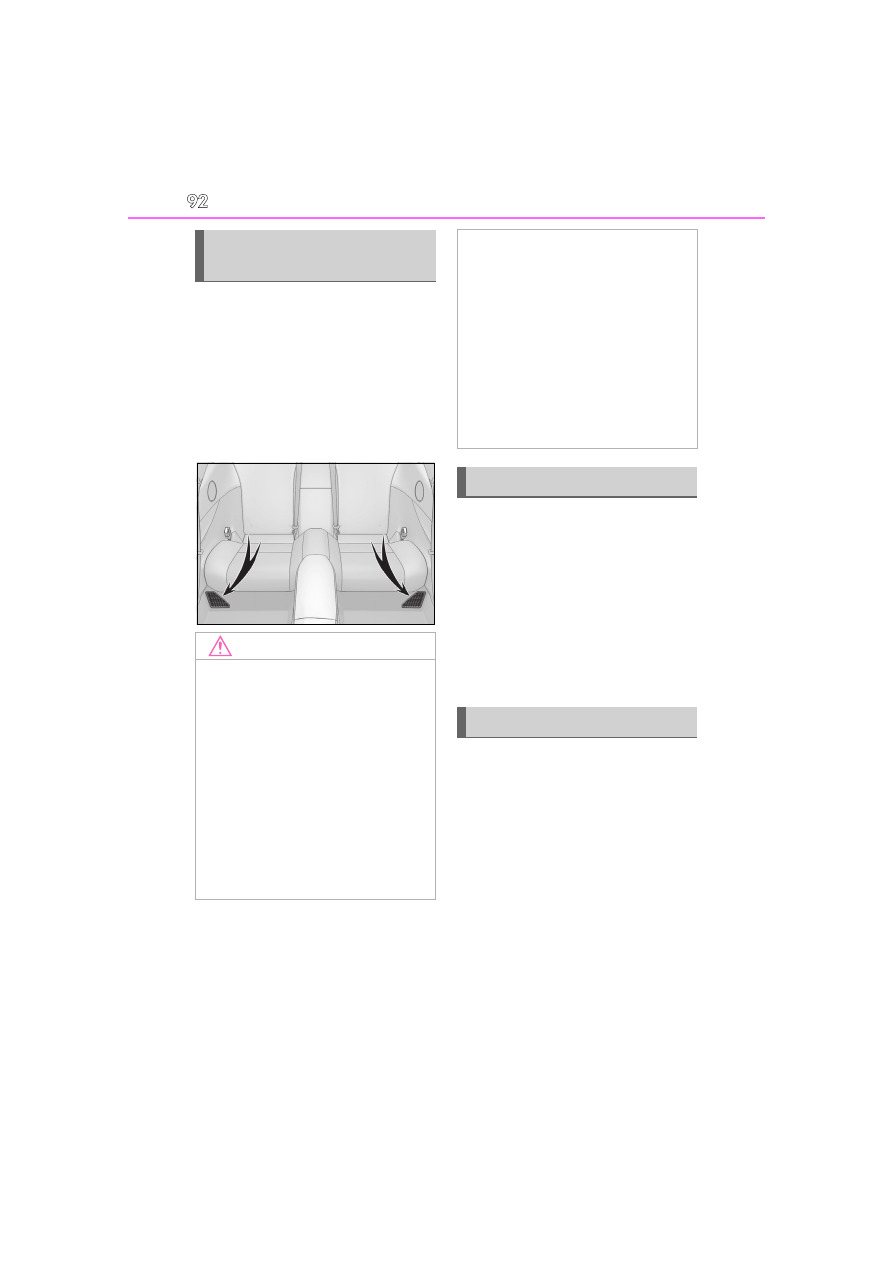
There are air intake vents under the 
rear seats for the purpose of cooling 
the hybrid battery (traction battery). If 
the vents become blocked, the hybrid 
battery input and output may be 
restricted, leading to a reduction in 
hybrid battery (traction battery) out-
put.

When a certain level of impact is 
detected by the impact sensor, the 
emergency shut off system blocks the 
high voltage current and stops the fuel 
pump to minimize the risk of electrocu-
tion and fuel leakage. If the emergency 
shut off system activates, your vehicle 
will not restart. To restart the hybrid 
system, contact your Lexus dealer.

A message is automatically displayed 
when a malfunction occurs in the 
hybrid system or an improper opera-
tion is attempted.
If a warning message is shown on the 
multi-information display, read the 
message and follow the instructions.

Hybrid battery (traction battery) 
air intake vents

NOTICE

Hybrid battery (traction battery) air 

intake vents

Make sure not to block the air intake 

vent with anything, such as a seat 

cover, plastic cover, or luggage. If the 

vents become blocked, the hybrid bat-

tery (traction battery) input and output 

may be restricted, leading to a reduc-

tion in hybrid battery (traction battery) 

output and a malfunction.

When dust etc. has accumulated in the 

air intake vent, periodically clean it 

with a vacuum cleaner to prevent the 

vent from clogging.

Filters are installed to the air intake 

vent. When the filters remain notice-

ably dirty even after cleaning the air 

intake vent, filter cleaning or replace-

ment is recommended. When clean-

ing or replacing the filters, contact 

your Lexus dealer. 

Refer to P.324 for details on how to 

clean the filters.

Do not get water or foreign materials 

in the air intake vents as this may cause 

a short circuit and damage the hybrid 

battery (traction battery).

Emergency shut off system

Hybrid warning message

93

1-4. Hybrid system

1

For safety and security

If a warning light comes on, a warning 

message is displayed, or the 12-volt bat-

tery is disconnected

The hybrid system may not start. In this 

case, try to start the system again. If the 

“READY” indicator does not come on, con-

tact your Lexus dealer.

94

1-5. Theft deterrent system

1-5.Theft deterrent system

The indicator light flashes after the 
engine switch <power switch> has been 
turned off to indicate that the system is 
operating.
The indicator light stops flashing after 
the engine switch <power switch> has 
been turned to ACC or ON to indi-
cate that the system has been can-
celed.

System maintenance

The vehicle has a maintenance-free type 

engine immobilizer system <immobilizer 

system>.

Conditions that may cause the system to 

malfunction

If the grip portion of the key is in contact 

with a metallic object

If the key is in close proximity to or touch-

ing a key registered to the security sys-

tem (key with a built-in transponder chip) 

of another vehicle

Engine immobilizer system 
<Immobilizer system>

The vehicle’s keys have built-in 
transponder chips that prevent the 
engine <hybrid system> from start-
ing if a key has not been previously 
registered in the vehicle’s on-board 
computer.
Never leave the keys inside the 
vehicle when you leave the vehicle.

This system is designed to help pre-
vent vehicle theft but does not guar-
antee absolute security against all 
vehicle thefts.

Operating the system

NOTICE

To ensure the system operates cor-

rectly

Do not modify or remove the system. If 

modified or removed, the proper opera-

tion of the system cannot be guaranteed.

95

1-5. Theft deterrent system

1

For safety and security

Items to check before locking the 
vehicle

To prevent unexpected triggering of 
the alarm and vehicle theft, make sure 
of the following:

Nobody is in the vehicle.

The windows are closed before the 
alarm is set.

No valuables or other personal 
items are left in the vehicle.

Setting

Close the doors, trunk and hood, and 
lock both side doors. The system will 
be set automatically after 30 seconds.

The indicator light changes from being on 
to flashing when the system is set.

Canceling or stopping

Do one of the following to deactivate 
or stop the alarms:

Except for Canada: Unlock the 
doors or open the trunk.

For Canada: Unlock the doors using 
the entry function or wireless 
remote control.

Turn the engine switch <power 
switch> to ACC or ON, or start the 
engine <hybrid system>. (The alarm 
will be deactivated or stopped after 
a few seconds.)

System maintenance

The vehicle has a maintenance-free type 

alarm system.

Triggering of the alarm

The alarm may be triggered in the following 

situations: 

(Stopping the alarm deactivates the alarm 

system.)

Convertible for Canada: The doors are 

unlocked using the mechanical key.

Alarm

The alarm uses light and sound to 
give an alert when an intrusion is 
detected. 
The alarm is triggered in the follow-
ing situations when the alarm is set:

Except for Canada: A locked 
door or trunk is unlocked or 
opened in any way other than 
using the entry function, wireless 
remote control or mechanical 
key. (The doors will lock again 
automatically.)

For Canada: A locked door or 
trunk is unlocked or opened in 
any way other than using the 
entry function or wireless remote 
control. (The door will lock again 
automatically.)

The hood is opened.

Setting/canceling/stopping the 
alarm system

96

1-5. Theft deterrent system

A person inside the vehicle opens a door, 

the trunk or hood, or unlocks the vehicle 

using a door lock switch.

The 12-volt battery is recharged or 

replaced when the vehicle is locked. 

(

P.422)

Alarm-operated door lock

In the following cases, depending on the sit-

uation, the door may automatically lock to 

prevent improper entry into the vehicle:

When a person remaining in the vehicle 

unlocks the door and the alarm is acti-

vated.

While the alarm is activated, a person 

remaining in the vehicle unlocks the door.

When recharging or replacing the 12-

volt battery

Customization

The alarm can be set to activate/deactivate 

when the mechanical key is used to unlock. 

(Customizable features: 

P.459)

NOTICE

To ensure the system operates cor-

rectly

Do not modify or remove the system. If 

modified or removed, the proper opera-

tion of the system cannot be guaranteed.

97

1-5. Theft deterrent system

1

For safety and security

Theft prevention labels 
(U.S.A.)

These labels are attached to the 
vehicle to reduce vehicle theft by 
facilitating the tracing and recov-
ery of parts from stolen vehicles. 
Do not remove under penalty of 
law.

98

1-5. Theft deterrent system

99

2

2

Vehi

cle

 status 

inform

ati

on a

nd i

ndic
ators

Vehicle status information

and indicators

2-1. Instrument cluster

Warning lights and indicators

.........................................................

100

Gauges and meters ..................

106

Multi-information display.........

110

Head-up display ..........................

117

Energy monitor/consumption 

screen ..........................................

122

100

2-1. Instrument cluster

2-1.Instrument cluster

For the purpose of explanation, the following illustrations display all warning lights 
and indicators illuminated.

LC500

LC500h

The units used on the meters and some indicators may differ depending on the target 
region.

Warning lights and indicators

The warning lights and indicators on the instrument cluster, center panel and 
outside rear view mirrors inform the driver of the status of the vehicle’s vari-
ous systems.

Instrument cluster

101

2-1. Instrument cluster

2

Vehi

cle

 status 

inform

ati

on a

nd i

ndic
ators

Warning lights inform the driver of 
malfunctions in the indicated vehicle 
systems.

*1

: These lights turn on when the engine 

switch <power switch> is turned to ON 

Warning lights

(U.S.A.)

Brake system warning light

*1


(

P.385)

(red)

(Canada)

Brake system warning light

*1


(

P.385)

Charging system warning 
light

*2

 (

P.385)

Low engine oil pressure 
warning light

*2

 (

P.385)

(U.S.A.)

Malfunction indicator lamp

*1


(

P.386)

(Canada)

Malfunction indicator lamp

*1


(

P.386)

SRS warning light

*1


(

P.386)

(U.S.A.)

ABS warning light

*1


(

P.386)

(Canada)

ABS warning light

*1


(

P.386)

(red)

Electric power steering sys-
tem warning light

*1


(

P.386)

(yellow)

Electric power steering sys-
tem warning light

*1


(

P.386)

(Flashes or 

illuminates)

PCS warning light

*1


(

P.387)

(orange)

LTA indicator (

P.387)

Slip indicator

*1

 (

P.387)

Brake Override System 
warning light 
(

P.388)/Drive-Start Con-

trol warning light

*2


(

P.388)

Brake hold operated indica-
tor

*1, 3

 (

P.388)

(U.S.A.)

Parking brake indicator

*3


(

P.388)

(Canada)

Parking brake indicator

*3


(

P.388)

(yellow)

Brake system warning light

*1


(

P.389)

Low fuel level warning light 
(

P.389)

Driver’s and front passen-
ger’s seat belt reminder light 
(

P.389)

Rear passengers’ seat belt 
reminder lights (

P.389)

Master warning light

*1


(

P.390)

Tire pressure warning light

*1, 

3

 (

P.390)

High coolant temperature 
warning light

*2

 (

P.390)

(if equipped)

Hybrid system overheat 
warning light

*2

(

P.391)

102

2-1. Instrument cluster

to indicate that a system check is being 
performed. They will turn off after the 
engine <hybrid system> is started, or 
after a few seconds. There may be a 
malfunction in a system if a light does 
not come on, or turn off. Have the vehi-
cle inspected by your Lexus dealer.

*2

: This light illuminates on the multi-infor-

mation display.

*3

: The light flashes to indicate a malfunc-

tion.

The indicators inform the driver of the 
operating state of the vehicle’s various 
systems.

Operation indicators

WARNING

If a safety system warning light does 

not come on

Should a safety system light such as the 

ABS and SRS warning light not come on 

when you start the engine <hybrid sys-

tem>, this could mean that these systems 

are not available to help protect you in an 

accident, which could result in death or 

serious injury. Have the vehicle 

inspected by your Lexus dealer immedi-

ately if this occurs.

Indicators

Turn signal indicator 
(

P.203)

(U.S.A.)

Headlight indicator 
(

P.208)

(Canada)

Tail light indicator (

P.208)

Headlight high beam indica-
tor (

P.210)

AHB indicator

*1

 (

P.211)

Cruise control indicator

*2


(

P.247)

Dynamic radar cruise control 
indicator

*2

 (

P.247)

Cruise control “SET” indica-
tor

*2

 (

P.247)

(white)

LTA indicator

*3

 (

P.240)

(green)

LTA indicator

*3

 (

P.225, 

240)

(orange)

LTA indicator

*3

 (

P.240)

(if equipped)

Intuitive parking assist indica-
tor (

P.259)

Slip indicator

*1, 4

 (

P.281)

VSC OFF indicator

*1


(

P.281)

PCS warning light

*1, 5


(

P.225)

BSM (Blind Spot Monitor) 
outside rear view mirror indi-
cators

*6, 7

 (

P.266)

BSM (Blind Spot Monitor) 
indicator (

P.266)

RCTA (Rear Cross Traffic 
Alert) indicator (

P.266)

Brake hold standby indica-
tor

*1

 (

P.206)

Brake hold operated indica-
tor

*1

 (

P.206)

Security indicator

*8

 (

P.94, 

95)
Smart access system with 
push-button start indicator

*2


(

P.180, 184)

103

2-1. Instrument cluster

2

Vehi

cle

 status 

inform

ati

on a

nd i

ndic
ators

*1

: These lights turn on when the engine 

switch <power switch> is turned to ON 
to indicate that a system check is being 
performed. They will turn off after the 
engine <hybrid system> is started, or 
after a few seconds. There may be a 
malfunction in a system if a light does 
not come on, or turn off. Have the vehi-
cle inspected by your Lexus dealer.

*2

: This light illuminates on the multi-infor-

mation display.

*3

: Depending on the operating condition, 

the color and illuminating/flashing state 
of the light change.

*4

: The light flashes to indicate that the sys-

tem is operating.

*5

: The light comes on when the system is 

turned off.

*6

: In order to confirm operation, the BSM 

outside rear view mirror indicators illu-
minate in the following situations: 
When the engine switch <power 
switch> is turned to ON while the BSM 
main switch is turned on. 
When the BSM main switch is turned 
on while the engine switch <power 
switch> is in ON. 

(if equipped)

“READY” indicator 
(

P.184)

Low outside temperature 
indicator

*2, 9

 (

P.106)

(if equipped)

Eco Driving Indicator Light

*1


(

P.104)

(if equipped)

EV indicator (

P.87)

(U.S.A.)

Parking brake indicator 
(

P.204)

(Canada)

Parking brake indicator 
(

P.204)

Snow mode indicator 
(

P.194, 201)

(if equipped)

EV drive mode indicator 
(

P.188)

“Normal” indicator

*2


(

P.257)

“Eco” indicator

*2

 (

P.257)

“Sport S” indicator

*2


(

P.257)

“Sport S+” indicator

*2


(

P.257)

“Comfort” indicator

*2


(

P.257)

“Custom” indicator

*2


(

P.257)

“EXPERT” indicator

*2


(

P.281)

(U.S.A.)

“AIR BAG ON/OFF” indica-
tor

*8

 (

P.57)

(Canada)

“AIR BAG ON/OFF” indica-
tor

*8

 (

P.57)

104

2-1. Instrument cluster

If the system is functioning correctly, the 
BSM outside rear view mirror indica-
tors will turn off after a few seconds. 
If the BSM outside rear view mirror 
indicators do not illuminate or do not 
turn off, there may be a malfunction in 
the system. 
If this occurs, have the vehicle inspected 
by your Lexus dealer.

*7

: This light illuminates on the outside rear 

view mirrors.

*8

: This light illuminates on the center 

panel.

*9

: When the outside temperature is 

approximately 37°F (3°C) or lower, 
the indicator will flash for approximately 
10 seconds, then stay on.

Eco Driving Indicator (LC500)

Eco Driving Indicator Light

During Eco-friendly acceleration (Eco driv-
ing), the Eco Driving Indicator Light will 
turn on. When the acceleration exceeds the 
Zone of Eco driving, or when the vehicle is 
stopped, the light turns off.
Eco Driving Indicator can be enabled on 
the multi-information display. (

P.110)

Eco Driving Indicator Zone Display

Suggests the Zone of Eco driving with cur-
rent Eco driving ratio based on accelera-
tion.
When the driving mode is Normal mode or 
Comfort mode, switch the display to the 
side position. (

P.109)

Eco driving ratio based on acceleration

The part that exceeds the Zone of Eco driv-
ing illuminates in white.

Zone of Eco driving

Eco Driving Indicator will not operate 

under the following conditions:

The shift position is in any position other 

than D.

A paddle shift switch is operated.

The driving mode is SPORT S mode or 

SPORT S+ mode.

The vehicle speed is approximately 80 

mph (130 km/h) or higher.

Hybrid System Indicator (LC500h)

Charge area

Shows regeneration

*

 status. Regenerated 

energy will be used to charge the hybrid 
battery (traction battery).

Hybrid Eco area

Shows that gasoline engine power is not 

A

B

C

D

A

B

105

2-1. Instrument cluster

2

Vehi

cle

 status 

inform

ati

on a

nd i

ndic
ators

being used very often.
The gasoline engine will automatically stop 
and restart under various conditions.

Eco area

Shows that the vehicle is being driven in an 
Eco-friendly manner.
By keeping the indicator needle within Eco 
area, more Eco-friendly driving can be 
achieved.

Power area

Shows that an Eco-friendly driving range is 
being exceeded (during full power driving 
etc.)
In the following situation, the Hybrid System 
Indicator does not operate.

*

: When used in this manual, “regeneration” 

refers to the conversion of energy cre-
ated by the movement of the vehicle into 
electrical energy.

The shift position is in other than D or M.

The driving mode is other than Eco 

mode.

Motor power display (LC500h)

Motor power area

Shows that the power of the motor assists 
the engine.

Charge area

Shows regeneration

*

 status. Regenerated 

energy will be used to charge the hybrid 
battery (traction battery).

*

: When used in this manual, “regeneration” 

refers to the conversion of energy cre-
ated by the movement of the vehicle into 
electrical energy.

C

D

A

B

106

2-1. Instrument cluster

LC500

LC500h

The units used on the meters may differ depending on the target region.

Engine oil temperature gauge/Eco Driving Indicator (LC500)

Displays the engine oil temperature or Eco Driving Indicator (

P.104)

Outside temperature

Gauges and meters

When the main meter is in the side position, some of the meter displays and 
the gauge layout will be changed.

Meter display

A

B

107

2-1. Instrument cluster

2

Vehi

cle

 status 

inform

ati

on a

nd i

ndic
ators

Displays the outside temperature within the range of -40°F (-40°C) to 122°F (50°C) 
Low outside temperature indicator comes on when the ambient temperature is 37°F 
(3°C) or lower

Tachometer

Displays the engine speed in revolutions per minute

Speedometer

Shift position/shift range/gear position (

P.190, 196)

Shift position indicator (

P.191, 198)

Clock

Engine coolant temperature gauge

Displays the engine coolant temperature 
If the engine coolant temperature gauge indicator enters the red zone, a buzzer sounds 
and the high coolant temperature warning light comes on

Odometer and trip meter display

Odometer: 
Displays the total distance the vehicle has been driven
Trip meter: 
Displays the distance the vehicle has been driven since the meter was last reset 
Trip meters “A” and “B” can be used to record and display different distances inde-
pendently

Fuel gauge

Displays the quantity of fuel remaining in the tank

Multi-information display

Presents the driver with a variety of vehicle data (

P.110)

Displays warning messages in case of a malfunction (

P.394)

Motor power display/Hybrid System Indicator (LC500h)

Displays the motor power display (

P.105) or Hybrid System Indicator (

P.104)

Rev indicator

When the engine speed reaches a set 
speed or the red zone, a ring-shaped 
indicator will be displayed on the 
tachometer.
The indicators will be displayed in 
amber (

) when the engine speed 

reaches a set speed, and in red (

when the engine speed reaches the 
red zone. This setting can be enabled 
on the multi-information display. 
(

P.115)

C

D

E
F

G

H

I

J

K

L

A

B

108

2-1. Instrument cluster

Rev peak

When the engine speed reaches or 
exceeds the following, an afterimage of 
the tachometer will be displayed at the 
highest engine speed for approxi-
mately 1 second.
LC500: 3600 r/min
LC500h: 4000 r/min

The meters and display illuminate when

The engine switch <power switch> is in ON.

Variable red zone (LC500)

To help protect the engine, the engine 

speed is controlled by starting the red zone 

of the tachometer at different engine 

speeds ranging from 3700 rpm to 7300 

rpm depending on the engine coolant tem-

perature. 

Before driving under extremely high load 

conditions, make sure to sufficiently warm 

up the engine.

Instrument panel brightness adjustment

The brightness of the instrument panel 

lights is automatically adjusted based on the 

light sensor detecting how bright the sur-

roundings are.

Outside temperature display

In the following situations, the correct 

outside temperature may not be dis-

played, or the display may take longer 

than normal to change.

• When stopped, or driving at low speeds 

(less than 12 mph [20 km/h])

• When the outside temperature has 

changed suddenly (at the entrance/exit 

of a garage, tunnel, etc.)

When “- -” or “E” is displayed, the system 

may be malfunctioning. 

Take your vehicle to your Lexus dealer.

Speed unit setting for the speedometer

When the speed unit has been changed 

from the default setting, the vehicle speed in 

the default unit is also displayed in the 

meter.

Pop-up display

In some situations, such as when a switch 

operation is performed, a pop-up display 

will be temporarily displayed on the 

multi-information display.

Some pop-up displays can be set on/off. 

(

P.114)

109

2-1. Instrument cluster

2

Vehi

cle

 status 

inform

ati

on a

nd i

ndic
ators

Liquid crystal display

Small spots or light spots may appear on the 

display. This phenomenon is characteristic 

of liquid crystal displays, and there is no 

problem continuing to use the display.

Customization

The meter display can be customized on 

the multi-information display. (

P.459)

The odometer and trip meter displays 
can be switched. When the trip meter 
is displayed, pressing and holding the 
button will reset the trip meter.

The brightness of the instrument panel 
lights can be adjusted.

1

Darker

2

Brighter

Instrument panel brightness adjustment

The instrument panel brightness levels 

when the tail lights are on and off can be 

adjusted individually. However, when the 

surroundings are bright (daytime, etc.), 

turning on the tail lights will not change the 

instrument panel brightness.

The display can be switched between 
the center and side positions.

NOTICE

To prevent damage to the engine and 

its components

Do not let the indicator of the tachom-

eter enter the red zone, as it rep-

resents the engine speed range which 

exceeds the maximum safe engine 

speed.

In the following situations, the engine 

may be overheating. In this case, 

immediately stop the vehicle in a safe 

place, and check the engine after it has 

cooled completely. (

P.431, 433)

• The engine coolant temperature 

gauge is in the red zone (H).

• LC500: The engine oil temperature 

gauge is in the red zone (H).

Changing between the odome-
ter and trip meter

Changing the Instrument panel 
light brightness

Changing the display

110

2-1. Instrument cluster

Display

When the main meter is in the cen-
ter position

Displays various drive information on 
the main meter.
Some of the contents which are dis-
played when the main meter is in the 
side position cannot be displayed. 
(

P.112)

When the main meter is in the side 
position

Selecting a menu icon displays a vari-
ety of vehicle data or allows vehicle 
settings to be customized.

Menu icons

Multi-information display

Display and menu icons

Drive information (

P.112)

Navigation system-linked dis-
play (

P.114)

Audio system-linked display 
(

P.114)

Driving support system infor-
mation display (

P.114)

111

2-1. Instrument cluster

2

Vehi

cle

 status 

inform

ati

on a

nd i

ndic
ators

Opening image display

When the engine switch <power switch> is 

in ACC or ON, the opening image is dis-

played on the multi-information display. 

While the opening image is being dis-

played, the meter display cannot be 

changed even if the drive mode is changed. 

When the start-up display is finished, the 

meter display for the currently selected 

mode will be displayed.

When disconnecting and reconnecting 

12-volt battery terminals

Record of the maximum G-forces will be 

reset.

Liquid crystal display

P.109

The multi-information display is oper-
ated using the meter control switches.

/

: Switch menu 

/

: Change displayed con-

tent, scroll up/down the screen and 
move the cursor up/down

Press: Enter/Set 
Press and hold: Reset

Return to the previous screen and 
move the main meter

Call sending/receiving and history 
display 
Linked with the hands-free system, 
sending or receiving call is dis-
played. For details regarding the 

Warning message display 
(

P.394)

Settings display (

P.114)

WARNING

Caution for use while driving

When operating the multi-information 

display while driving, pay extra atten-

tion to the safety of the area around 

the vehicle.

Do not look continuously at the multi-

information display while driving as 

you may fail to see pedestrians, objects 

on the road, etc. ahead of the vehicle.

The information display at low tem-

peratures

Allow the interior of the vehicle to warm 

up before using the liquid crystal infor-

mation display. At extremely low tem-

peratures, the information display 

monitor may respond slowly, and display 

changes may be delayed. 

For example, there is a lag between the 

driver’s shifting and the new gear num-

ber appearing on the display. This lag 

could cause the driver to downshift 

again, causing rapid and excessive 

engine braking and possibly an accident 

resulting in death or injury.

Changing the meter display

A

B

C

D

112

2-1. Instrument cluster

hands-free system, refer to “MUL-
TIMEDIA OWNER’S MANUAL”.

Content of drive information

Select to display various drive data.
Up to 2 of the following items can be 
selected.
Items displayed can be switched by 
pressing 

 or 

 of the meter con-

trol switches to select 

 and pressing 

 or 

.

Current fuel consumption

*1

Displays the current rate of fuel consump-
tion

Average fuel economy (after 
reset

*2

/after start/after refuel)

*1

Displays the average fuel consumption 
since the function was reset, the engine 
<hybrid system> was started, and the vehi-
cle was refueled, respectively
Use the displayed average fuel consump-
tion as a reference.

Average speed (after reset

*2

/after 

start)

*1

Displays the average vehicle speed since 
the function was reset and the engine 
<hybrid system> was started, respectively

Elapsed time (after reset

*2

/after 

start)

*1

Displays the elapsed time since the func-
tion was reset and the engine <hybrid sys-
tem> was started, respectively

Distance (range/after start)

*1

Displays the estimated maximum distance 
that can be driven with the quantity of fuel 
remaining and the distance driven after the 
engine <hybrid system> was started 
respectively.
• This distance is computed based on your 

average fuel consumption. As a result, 
the actual distance that can be driven 
may differ from that displayed.

• When only a small amount of fuel is 

added to the tank, the display may not be 
updated. 
When refueling, turn the engine switch 
<power switch> off. If the vehicle is refu-
eled without turning the engine switch 
<power switch> off, the display may not 
be updated.

*1

: Displayed when the item is set in “Drive 

Info 1” and “Drive Info 2”.

*2

: The function can be reset by pressing 

“OK” of the meter control switches for 
longer than 1 second when the item to 
reset is displayed. 
If there is more than one item that can 
be reset, the item selection screen will 
appear.

Eco Driving Indicator/engine oil 
temperature gauge (LC500)

P.104, 106

Hybrid System Indicator/motor 
power display (LC500h)

P.104

Energy monitor (LC500h)

P.122

Tire pressure

P.351

Gear positions

Displays the current shift range or gear 
position when the shift position is in D 

Drive information

113

2-1. Instrument cluster

2

Vehi

cle

 status 

inform

ati

on a

nd i

ndic
ators

or M.

Units

The units of measure used can be 
changed while driving.

Unlike the units setting performed on the 
settings display, the units setting per-
formed on the drive information menu can 
be changed while driving.

G-force

Displays lateral G-forces on the vehi-
cle

Reading the display

• Normal display
Displays the following on the multi-infor-
mation display

Acceleration G-force on the vehicle

Current G-force value (analyzed value 
of front/rear and left/right G-forces)

• Advanced display
Displays the following on the main meter 
and multi-information display
Multi-information display:

Acceleration G-force on the vehicle

Record of the maximum G-forces

Value of the maximum G-force since 
display reset (analyzed value of 
front/rear and left/right G-forces)

This display is intended for use as a guide-
line. Depending on factors such as the 
road surface condition, temperature and 
vehicle speed, the display may not show 
the actual condition of the vehicle.
Main meter:

G-force direction

Current G-force value (analyzed value 
of front/rear and left/right G-forces)

This display is intended for use as a guide-
line. Depending on factors such as the 
road surface condition, temperature and 
vehicle speed, the display may not show 
the actual condition of the vehicle.

Switching the display

To switch to advanced display, press “OK”.

A

B

A

B

C

A

B

114

2-1. Instrument cluster

To return to normal display, press “OK”.

Resetting the record of maximum 
G-forces

With the record of maximum G-forces dis-
played, press and hold “OK” to reset the 
display.

Peak hold function (advanced dis-
play only)

If lateral G-forces of 0.5 G or greater are 
generated, the G-force value displayed on 
the main meter will turn yellow and be held 
for 3 seconds.

Rear wing position (if equipped)

Displays the raised/retracted state of 
the active rear wing

Display off

A blank screen is displayed

Select to display the following naviga-
tion system-linked information.

Route guidance

Compass display

Select to enable selection of an audio 
source or track on the meter using the 

meter control switches.

Select to display the operational status 
of the following systems:

LTA (Lane Tracing Assist) 
(

P.235)

Dynamic radar cruise control with 
full-speed range (

P.247)

RSA (Road Sign Assist) (if 
equipped) (

P.244)

Select to display warning messages 
and measures to be taken if a malfunc-
tion is detected. (

P.394)

Select to change the meter display set-
tings.

Language

Select to change the language on the 
display.

Units

Select to change the unit of measure 
for fuel consumption.

Eco Driving Indicator Light 
(LC500)

Select to activate/deactivate the Eco 
Driving Indicator Light.

EV indicator (LC500h)

Select to activate/deactivate the EV 
indicator.

Navigation system-linked dis-
play

Audio system-linked display

Driving support system informa-
tion display

Warning message display

Settings display

115

2-1. Instrument cluster

2

Vehi

cle

 status 

inform

ati

on a

nd i

ndic
ators

Drive information 1/Drive informa-
tion 2

Select to select up to 2 items that will 
be displayed on the “Drive Info 1” 
screen and “Drive Info 2” screen 
respectively. (

P.112)

Pop-up display

Select to set the following pop-up dis-
plays, which may appear in some situa-
tions, on/off.
• Route guidance display of the navi-

gation system-linked system

• Making call display of the hands-

free phone system

• Audio system operation display
• Voice recognition display
• Instrument panel brightness adjust-

ment display

Ring position memory

Select to change the meter ring posi-
tion when the engine <hybrid system> is 
started.
The position before the engine <hybrid 
system> is stopped or the center posi-
tion can be selected.

Accent color

Select to change the accent color on 
the screen, such as the cursor color.

Rev indicator

Select to set the rev indicator on/off.
When set to on, proceed to select the 
engine speed at which the rev indica-
tor will be displayed.

Rev peak

Select to set the rev peak on/off.

Clock

Select to switch between 12-hour dis-
play and 24-hour display.

Initialization

Select to reset the meter display set-
tings.

Suspension of the settings display

In the following situations, operation of the 

settings display will be temporarily sus-

pended.

When a warning message appears on the 

multi-information display

When the vehicle begins to move

Customization

The settings can be changed on 

 of the 

multi-information display.

Settings of the driving assist systems 

(

P.459)

Vehicle settings (

P.118, 330, 353, 

355, 459)

WARNING

Cautions during setting up the dis-

play

As the engine <hybrid system> needs to 

be running <operating> during setting up 

the display, ensure that the vehicle is 

parked in a place with adequate ventila-

tion. In a closed area such as a garage, 

exhaust gases including harmful carbon 

monoxide (CO) may collect and enter 

the vehicle. This may lead to death or a 

serious health hazard.

NOTICE

While setting up the display

To prevent 12-volt battery discharge, 

ensure that the engine is running <hybrid 

system is operating> while setting up the 

display features.

116

2-1. Instrument cluster

Displays suggestions to the driver in 
the following situations. For some sug-
gestions, a response to a displayed 
suggestion can be selected. To select a 
response, use the meter control 
switches.

Suggestion to turn on the head-
lights

If the headlight switch is in other than 

 or 

 position, and the vehicle 

speed is 3 mph (5 km/h) or higher for 
a certain amount of time when the sur-
roundings are dark, a suggestion mes-
sage will be displayed.

Suggestion to turn off the head-
lights

If the headlights are left on for a certain 
amount of time after the engine switch 
<power switch> has been turned off, a 
suggestion message will be displayed 
asking if you wish to turn the headlights 
off.
When the headlight switch is in the 
“AUTO” position: To turn the head-
lights off, select “Yes”.

If a front door is opened after the engine 
switch <power switch> is turned off, this 
suggestion message will not be displayed.

Suggestion to unlock the power 
windows

If it is attempt to close the passenger’s 
side window using the power window 
switch on the driver’s door or all win-
dow control switch

*

, a suggestion mes-

sage will be displayed.

*

: Convertible

Customization

The suggestion function can be turned 

on/off. (Customizable features: 

P.459)

Suggestion function

117

2-1. Instrument cluster

2

Vehi

cle

 status 

inform

ati

on a

nd i

ndic
ators

*

: If  equipped

Navigation system-linked display 
area (

P.120)

RSA (Road Sign Assist) display 
area (if equipped) (

P.244)

Displays the following items, which are 
linked to the navigation system:
• Speed limit
• Street  name
• Route guidance to destination
• Compass

Driving support system status dis-

play area

Displays the current shift position, and shift 
range/gear position, or the operational 
status of the following systems:
• Pre-collision warning (Pre-Collision 

System) (

P.225)

• Dynamic radar cruise control with full-

speed range (

P.247)

• LTA (Lane Tracing Assist) (

P.235)

Displayed content is the same as that dis-
played on the multi-information display. 
For details, refer to the explanations of 
each system.

Vehicle speed display

Information display area (

P.119)

Displays the following items:
• Warning/message

/


icon  (

P.119)

• Audio system operation status
• Dynamic radar cruise control with full-

speed range status (

P.247)

• Hands-free system status (

P.119)

• Eco Driving Indicator/tachometer 

(

P.120) (LC500)

• Hybrid System Indicator/motor power 

display/tachometer (

P.121) 

(LC500h)

HUD (Head-up display) switch

Enabling/Disabling the head-up 
display

Pressing the switch turns the head-up 
display on/off.

Head-up display

*

The head-up display is linked to the 
meters and navigation system and 
projects a variety of information in 
front of the driver, such as the cur-
rent vehicle speed and route guid-
ance to a set destination.

System components

A

B

Using the head-up display

C
D

E

118

2-1. Instrument cluster

Changing settings of the head-up 
display

Select 

 on the multi-information dis-

play (

P.110) to change the following 

settings:

Display brightness/position

Select to adjust the brightness and position 
of the head-up display.

Eco Driving Indicator/tachometer 
(LC500)

Select to display Eco Driving Indicator, 
tachometer or no content.

Hybrid System Indicator/motor 
power display/tachometer 
(LC500h)

Select to display Hybrid System Indicator, 
tachometer or no content.
Motor power display can be displayed 
when Hybrid System Indicator is selected 
while the driving mode (

P.257) is other 

than the Eco drive mode.

Display content

Select to enable/disable the following 
items:
• Route guidance to destination
• Driving assist system status
• Compass
• Audio system operation status

Display angle

Select to adjust the angle of the head-up 
display.

Head-up display

The head-up display may seem dark and 

hard to see when viewed through sun-

glasses, especially polarized sunglasses. 

Adjust the brightness of the head-up dis-

play or remove your sunglasses.

When the head-up display is turned off, it 

will remain off even if the engine switch 

<power switch> is turned to ACC or ON 

after the engine switch <power switch> 

has been turned off.

The startup image will be displayed on 

the head-up display after the engine 

switch <power switch> has been turned to 

ON while the head-up display switch is 

set to on.

Display brightness

The brightness of the head-up display can 
be adjusted on 

 of the multi-information 

display. Also, it is automatically adjusted 
according to the ambient brightness.

Head-up display automatic position 

adjustment

If the display position is recorded into mem-

ory, the head-up display will be automati-

cally adjusted to the desired position. 

(

P.145)

When the 12-volt battery is discon-

nected

The customize settings of the head-up dis-

play will be reset.

Customization

Settings (e.g. display) can be changed. 

(Customizable features: 

P.459)

119

2-1. Instrument cluster

2

Vehi

cle

 status 

inform

ati

on a

nd i

ndic
ators

Displays the following items in the 
appropriate situation:

Warning/message

Displays the following warning/mes-
sages:
• Master warning message
• Notification message (Dynamic 

radar cruise control with full-speed 
range)

• Other messages

/

 icons

Displays the following multi-informa-
tion display linked icons:

: Master warning icon

Displayed when a warning message is dis-
played on the multi-information display. 
(

P.394)

: Information icon

Displayed when a suggestion/advice pop-
up display is displayed on the multi-infor-
mation display. (

P.116)

Hands-free system status

Displayed when the hands-free system 
is operated.

WARNING

Before using the head-up display

Check that the position and brightness 

of the head-up display image does not 

interfere with safe driving. Incorrect 

adjustment of the image’s position or 

brightness may obstruct the driver’s 

view and lead to an accident, resulting 

in death or serious injury.

Do not continuously look at the head-

up display while driving as you may fail 

to see pedestrians, objects on the 

road, etc. ahead of the vehicle.

Caution for changing settings of the 

head-up display

As the engine needs to be running 

<hybrid system needs to be operating> 

while changing the settings of the head-

up display, ensure that the vehicle is 

parked in a place with adequate ventila-

tion. In a closed area such as a garage, 

exhaust gases including harmful carbon 

monoxide (CO) may collect and enter 

the vehicle. This may lead to death or a 

serious health hazard.

NOTICE

To prevent damage to components

Do not place any drinks near the head-

up display projector. If the projector 

gets wet, electrical malfunctions may 

result.

Do not place anything on or put stick-

ers onto the head-up display projector. 

Doing so could interrupt head-up dis-

play indications.

Do not touch the inside of the head-up 

display projector or thrust sharp edges 

or the like into the projector. 

Doing so could cause mechanical mal-

functions.

When changing the settings of the 

head-up display

To prevent battery discharge, ensure 

that the engine is running while changing 

the settings of the head-up display.

Information display area

120

2-1. Instrument cluster

Audio system operation status

Displayed when the audio system is 
operated.

Eco Driving Indicator/tachometer 
(LC500)

Displays either of Eco Driving Indica-
tor or the tachometer.

Hybrid System Indicator/motor 
power display/tachometer 
(LC500h)

Displays either of Hybrid System Indi-
cator or the tachometer.
Motor power display can be displayed 
when Hybrid System Indicator is 
selected while the driving mode 
(

P.257) is other than the Eco drive 

mode.

Displays the following items which are 
linked to the navigation system:

Speed limit

Displays the speed limit on the current 
road.

Street name

When the navigation system is per-
forming route guidance, the name of 
the next street will be displayed on the 
top of the display area.

Route guidance to destination

Displayed when the navigation system 
is performing route guidance. When 
approaching an intersection, an arrow 
will be displayed to indicate the sug-

gested direction of travel.

Compass

Displays the direction of travel.

Street name display

Only street names which are included in the 

map data will be displayed.

Warning/suggestion/advice message 
or the operating state of a relevant sys-
tems will be displayed when necessary.

PCS (Pre-Collision System) 
(

P.225)

Brake Override System (

P.171)

Drive-Start Control (DSC) 
(

P.171)

When a pop-up display is displayed

When a pop-up display is displayed, a cur-

rent display may no longer be displayed. In 

this case, the display will return after the 

pop-up display disappears.

Eco Driving Indicator

Eco Driving Indicator Zone Display

Eco driving ratio based on acceler-

Navigation system-linked dis-
play area

Pop-up display

Eco Driving Indicator/tachome-
ter (LC500)

A
B

121

2-1. Instrument cluster

2

Vehi

cle

 status 

inform

ati

on a

nd i

ndic
ators

ation

Zone of Eco driving

Displayed content is the same as that dis-
played on the multi-information display 
(Eco Driving Indicator). For details, refer to 
P.104.

Tachometer

Displays the engine speed in revolu-
tions per minute.

Hybrid System Indicator

Charge area

Hybrid Eco area

Eco area

Power area

Displayed content is the same as that dis-
played on the meter (Hybrid System Indi-
cator). For details, refer to P.104.

Motor power display

Charge area

Power area

Displayed content is the same as that dis-
played on the meter (Motor power dis-
play). For details, refer to P.105.
Motor power display can be displayed 
when Hybrid System Indicator is selected 
while the driving mode (

P.257) is other 

than the Eco drive mode.

Tachometer

Displays the engine speed in revolu-
tions per minute.

Hybrid System Indicator/motor 
power display/tachometer 
(LC500h)

C

A
B
C
D

A
B

122

2-1. Instrument cluster

*

: If  equipped

Multi-information display 
(LC500h)

Center Display

Meter control switches (LC500h)

The energy monitor can be used to 
check the vehicle drive status, hybrid 
system operation status and energy 
regeneration status.

Display procedure

Multi-information display

Press 

 or 

 of the meter control 

switches and select 

, and then press 

 or 

 to select the energy monitor 

display.

Center Display

1

Select 

 on the main menu.

2

Select “Energy flow”.

Reading the display

The arrows will appear in accordance 
with the energy flow. When there is no 
energy flow, arrows will not be dis-
played.

The color of the arrows will change as fol-
lows
Blue: When the hybrid battery (traction 
battery) is regenerated or charged.

Yellow

*1

/Orange

*2

: When the hybrid bat-

tery (traction battery) is in use.
Red: When the gasoline engine is in use.

*1

: Multi-information  display

*2

: Center  Display

Multi-information display

The image shows all the arrows as an 
example. The actual display will vary 
depending on conditions.

Gasoline engine

Hybrid battery (traction battery)

Tires

Energy monitor

*

/consump-

tion screen

You can view the status of your 
hybrid system (LC500h) and fuel 
consumption information on the 
multi-information display and Cen-
ter Display.

System components

Energy monitor (LC500h)

A

B
C

A
B
C


Content      ..     1      2      3      4      ..