Lexus RZ450E (2023 year). Manual in english - page 8
 

  Index      Manuals     Lexus RZ450E (2023 year). Manual in english


Search            copyright infringement  


Content      ..     6      7      8      9     ..


Lexus RZ450E (2023 year). Manual in english - page 8


243

5-1. Functions and displays of the meter

5

Vehi

cle

 status 

inform

ati

on a

nd i

ndic
ators

*1

: Displayed when the meter display type 

setting is set to display type 1

*2

: Displayed when the meter display type 

setting is set to display type 2

*3

: For details, refer to “MULTIMEDIA 

OWNER’S MANUAL”.

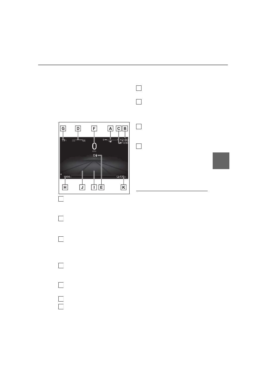
Vehicles with a head-up display (Bar 
display state

*1

)

SOC (State of Charge) gauge

Displays the amount of charge remaining 
in the traction battery.

Clock

Automatically adjusts the time by using the 
GPS time information (GPS clock).

*2

Navigation system estimated time 
of arrival display

Displays the estimated time of arrival 
according to the navigation system.

*2

Power meter

Displays EV system output or regeneration 
level. (

P.244)

Shift position/regenerative braking 
power indicator (

P.144, 150)

Digital speedometer
Outside temperature

Displays the ambient temperature within 
the range of -40°F (-40°C) to 141°F 
(60°C).

Odometer and trip meter display 
(

P.245)

Multi-information display

Presents the driver with a variety of vehicle 
data and displays warning messages if a 
malfunction occurs.

Background color of driving mode

Background color changes according to 
the driving mode.

Driving range

Displays the driving range with charge 
remaining in the traction battery.

*1

: Displayed when the meter display type 

setting is set to display type 3

*2

: For details, refer to “MULTIMEDIA 

OWNER’S MANUAL”.

The meters and display illuminate when

The power switch is in ON.

The meters and display change to bar 

display state when (vehicles with a 

head-up display)

The meters and display automatically 

change to bar display state when all of the 

following conditions are met:

LTA (Lane Tracing Assist) is enabled. 

(

P.291)

The dynamic radar cruise control is oper-

ating. (

P.318)

Outside temperature display

In the following situations, the correct 

outside temperature may not be dis-

played, or the display may take longer 

than normal to change:

• When stopped, or driving at low speeds 

(less than 16 mph [25 km/h])

• When the outside temperature has 

changed suddenly (at the entrance/exit of 

a garage, tunnel, etc.)

When “--” or “E” is displayed, the system 

A

B

C

D

E

F

G

H

I

J

K

244

5-1. Functions and displays of the meter

may be malfunctioning.

Take your vehicle to your Lexus dealer.

Driving range

When the air conditioning system is 
operating, 

 and the driving 

range with the air conditioning system on 

are displayed.

The driving range may shorten even 

when not driving due to power consump-

tion by the system.

Liquid crystal display

Small spots or light spots may appear on the 

display.
This phenomenon is characteristic of liquid 

crystal displays, and there is no problem 

continuing to use the display.

Free/Open Source Software Informa-

tion

This product contains Free/Open Source 

Software (FOSS). The license information 

and/or the source code of such FOSS can 

be found at the following URL.
https://www.denso.com/global/en/

opensource/meter/toyota/

Customization

Some functions can be customized. 

(

P.582)

This illustration is for explanation only 
and may differ depending on the speci-
fications of the vehicle.

Charge area

Shows regeneration

*1

 status.

Regenerated energy will be used to charge 
the EV battery (traction battery).

Power area

Displays the EV system output (accelera-
tion force) while driving.

Regeneration

*1

 restrictions refer-

ence display

*2

In the following situations, regenerative 
braking is restricted, and the references for 
those restrictions are displayed in the 
charge area.
• When the traction battery has a large 

amount of charge and can no longer be 
regenerated

• When the temperature of the traction 

batter is extremely high or extremely low

Output restrictions reference dis-
play

*2

In the following situations, the output is 
restricted, and the references for those 
restrictions are displayed in the power 

WARNING

Allow the interior of the vehicle to warm 

up before using the liquid crystal infor-

mation display. At extremely low tem-

peratures, the information display 

monitor may respond slowly, and display 

changes may be delayed.

For example, there is a lag between the 

driver’s shifting and the regenerative 

braking power appearing on the display. 

This lag could cause the driver to down-

shift again, causing rapid and excessive 

regenerative braking and possibly an 

accident resulting in death or injury.

Power meter

Power meter displays EV system 
output or regeneration level.

A

B

C

D

245

5-1. Functions and displays of the meter

5

Vehi

cle

 status 

inform

ati

on a

nd i

ndic
ators

area.
• When the traction battery has a low 

amount of charge and can no longer 
output power

• When the temperature of the traction 

batter is extremely high or extremely low

*1

: When used in this manual, “regenera-

tion” refers to the conversion of energy 
created by the movement of the vehicle 
into electrical energy.

*2

: The actual restrictions may differ 

depending on the vehicle condition.

The display can be changed between 
the following items.

Odometer

Displays the total distance the vehicle has 
been driven.

Trip meter A/trip meter B

Displays the distance the vehicle has been 
driven since the meter was last reset. Trip 
meters A and B can be used to record and 
display different distances independently.

Each time the switch is pressed, the 
displayed item will be changed.
When the trip meter is displayed, 
pressing and holding the switch will 

reset the trip meter.

Changing the distance driven 
display/resetting the distance 
driven

246

5-2. Functions of the displays

5-2.Functions of the displays

Content display area
Driving support system informa-
tion display area

When a menu icon other than 

 is 

selected, if the driving support system 
operates, the system operating state will be 
displayed. (

P.255)

By selecting menu icons on the 
multi-information display, the following 
items can be displayed.

 Driving information display 

(

P.252)

 Navigation system-linked 

display (

P.255)

 Audio system-linked dis-

play (

P.255)

 Driving support system 

information display (

P.255)

 Warning message 

(

P.256)

Liquid crystal display

Small spots or light spots may appear on the 

display. This phenomenon is characteristic 

of liquid crystal displays, and there is no 

problem continuing to use the display.

Changing the instrument panel light 

brightness

P.258

Multi-information display 
(vehicles without a head-up 
display)

A variety of driving-related infor-
mation can be displayed. Depend-
ing on the situation, warning or 
advice pop-up displays will also be 
displayed.

Display area

Items displayed in the content 
display area

A
B

WARNING

Caution for use while driving

When operating the multi-information 

display while driving, pay extra atten-

tion to the safety of the area around the 

vehicle.

Do not look continuously at the 

multi-information display while driving 

as you may fail to see pedestrians, 

objects on the road, etc. ahead of the 

vehicle.

The information display at low tem-

peratures

Allow the interior of the vehicle to warm 

up before using the liquid crystal infor-

mation display. At extremely low tem-

peratures, the information display 

monitor may respond slowly, and display 

changes may be delayed.

247

5-2. Functions of the displays

5

Vehi

cle

 status 

inform

ati

on 

an

indic
ators

Driving support system informa-
tion display area

When driving support system information 
is not displayed in the content display area, 
if the driving support system operates, the 
system operating state will be displayed. 
(

P.255)

Navigation system-linked display 
area

If the navigation system linked-display is 
not displayed in the content display area, 
route guidance will be displayed. 
(

P.255)

Content display area

The following items can be displayed.

WARNING

For example, there is a lag between the 

driver’s shifting and the regenerative 

braking power appearing on the display. 

This lag could cause the driver to down-

shift again, causing rapid and excessive 

regenerative braking and possibly an 

accident resulting in death or injury.

NOTICE

To prevent 12-volt battery discharge, 

ensure that the EV system is operating 

while setting up the display features.

Multi-information display 
(vehicles with a head-up dis-
play)

A variety of driving-related infor-
mation can be displayed. Depend-
ing on the situation, warning or 
advice pop-up displays will also be 
displayed.

Display area

Items displayed in the content 
display area

A

B

C

248

5-2. Functions of the displays

Drive information 1 (

P.252)

Drive information 2 (

P.253)

Audio system-linked display 
(

P.255)

Navigation system-linked dis-
play

*

(

P.255)

Driving support system information 
display

*

(

P.255)

Blank (No items) (

P.253)

*

: Displayed on the head-up display when 

the display mode is set to display the 
maximum.

Liquid crystal display

Small spots or light spots may appear on the 

display. This phenomenon is characteristic 

of liquid crystal displays, and there is no 

problem continuing to use the display.

Changing the instrument panel light 

brightness

P.258

WARNING

Caution for use while driving

When operating the multi-information 

display while driving, pay extra atten-

tion to the safety of the area around the 

vehicle.

Do not look continuously at the 

multi-information display while driving 

as you may fail to see pedestrians, 

objects on the road, etc. ahead of the 

vehicle.

The information display at low tem-

peratures

Allow the interior of the vehicle to warm 

up before using the liquid crystal infor-

mation display. At extremely low tem-

peratures, the information display 

monitor may respond slowly, and display 

changes may be delayed.

For example, there is a lag between the 

driver’s shifting and the regenerative 

braking power appearing on the display. 

This lag could cause the driver to down-

shift again, causing rapid and excessive 

regenerative braking and possibly an 

accident resulting in death or injury.

NOTICE

To prevent 12-volt battery discharge, 

ensure that the EV system is operating 

while setting up the display features.

249

5-2. Functions of the displays

5

Vehi

cle

 status 

inform

ati

on a

nd i

ndic
ators

*

: If  equipped

The content displayed will differ according to the driving conditions and display 
mode of the head-up display. Depending on the situation, pop-up displays will also 
be displayed.

Main display area

Displays the following items:
• Driving support system information display (

P.255)

• Power  meter  (

P.244)

• Compass
• Speed limit of the current road (linked to the navigation system) (U.S.A. only)

Driving information display area

Displays the following items:
• Speedometer
• Shift position/regenerative braking power indicator (

P.144

, 150

)

: Master warning icon

Displayed when a warning message is displayed.

Head-up display will operate when

The power switch is in ON.

When using the head-up display

The head-up display may seem dark or hard 

to see when viewed through sunglasses, 

especially polarized sunglasses. Adjust the 

brightness of the head-up display or 

remove your sunglasses.

The power meter is displayed when

When the following conditions are met, the 

power meter will be displayed on the 

head-up display.

Head-up display

*

The head-up display projects a variety of driving-related information and the 
operating state of the driving support systems on the windshield.

A

B

C

250

5-2. Functions of the displays

The head-up display is set to display the 

maximum. (

P.258)

LTA (Lane Tracing Assist) is dis-

abled.(

P.291)

LDA (Lane Departure Alert) is dis-

abled.(

P.590)

The cruise control, selected by pressing 

the driving assist mode select switch, is 

canceled. (

P.326, 328)

Customization

Some functions can be customized. 

(

P.258)

WARNING

Do not continuously look at the head-up 

display while driving as you may fail to 

see pedestrians, objects on the road, etc. 

ahead of the vehicle.

NOTICE

Observe the following precautions.

Do not place any drinks near the 

head-up display projector. If the pro-

jector gets wet, electrical malfunctions 

may result.

Do not place anything on or put stick-

ers onto the head-up display projector.

Doing so could interrupt head-up display 
indications.

Do not touch the inside of the head-up 

display projector or thrust sharp edges 

or the like into the projector.

Doing so could cause mechanical mal-
functions.

251

5-2. Functions of the displays

5

Vehi

cle

 status 

inform

ati

on a

nd i

ndic
ators

Vehicles without a head-up display

/

: Select menu icons

/

: Change displayed content, 

scroll up/down the screen and move the 
cursor up/down

Enter/Set
Return to the previous screen
Start/receive call

Linked with the hands-free system, sending 
or receiving call is displayed. For details 
regarding the hands-free system, refer to 
“MULTIMEDIA OWNER’S MANUAL”.

Vehicles with a head-up display

The function of each switch differs depending on the conditions and settings.

When a switch is touched, the function of each switch is displayed on the head-up display. If 
the head-up display is off, or when it is not possible to display content on the head-up dis-
play, the functions will be displayed on the multi-information display.
Also, preferred functions for each switch can be set on the center display.

Each time this switch is pressed, the functions will change.
Switch icon display

The icon of each switch will be displayed. The touched switch will be highlighted. (

)

Switch function guide display

The function guide for the touched switch will be displayed.

Displayed content

Operating the meters/displays

A

B
C
D

A

B
C

D

252

5-2. Functions of the displays

If the steering wheel switches do not 

respond when touched (vehicles with a 

head-up display)

It is easier to make the steering wheel 

switches respond by moving your thumb 

while touching them.

If the surface of a steering wheel switch is 

dirty, turn the power switch off and then 

clean the switches.

By turning winter glove mode on, the sen-

sitivity of the switch sensors can be 

increased. (

P.583)

Customization

Some functions can be customized. 

(

P.583)

1

Press 

 or 

 of the meter con-

trol switch.

1

Press the 

 or 

 meter control 

switch to select 

. Then press 


or .

1

Select 

 on the center display.

2

Select “Vehicle customize”.

3

Select “Meter”.

4

Select 

 or 

 of “Display 

switching”.

The display changes each time the switch is 

selected.

Switching with the steering wheel 

switches

If 

/

 is set as a favorite 

steering wheel switch function, the display 
can be switched by pushing 

 or 

.

Driving related information is dis-
played on the following displays.

Multi-information display

Head-up display (if equipped)

Center display

The items displayed will differ depend-
ing on the display.

The following items can be displayed 
on the multi-information display.
Use the displayed values as a refer-
ence only.

Current electricity consumption

Displays the instantaneous current elec-
tricity consumption.

Average electricity consumption

Electricity consumption

For U.S.A.

Electricity consumption is the consumption 
rate of the electricity and equivalent to the 
fuel consumption for the gasoline vehicles. 
For this vehicle, driven distance per kWh of 
electricity consumed (“miles/kWh”) is dis-
played as electricity consumption on each 

Switching the display of the 
multi-information display (vehi-
cles without a head-up display)

Switching driving information (vehi-
cles without a head-up display)

Switching the display of the 
multi-information display (vehi-
cles with a head-up display)

Display of drive information

Drive information 1

253

5-2. Functions of the displays

5

Vehi

cle

 status 

inform

ati

on a

nd i

ndic
ators

screen.

For Canada

Electricity consumption is the consumption 
rate of the electricity and equivalent to the 
fuel consumption for the gasoline vehicles. 
For this vehicle, electricity consumed per 
100 km (“kWh/100 km”) is displayed as 
electricity consumption on each screen.

The following items can be displayed 
on the multi-information display.

Average vehicle speed

Total driving time

Average electricity consumption since 
starting can be displayed on the 
multi-information display.

Electricity consumption

For U.S.A.

Electricity consumption is the consumption 
rate of the electricity and equivalent to the 
fuel consumption for the gasoline vehicles. 
For this vehicle, driven distance per kWh of 
electricity consumed (“miles/kWh”) is dis-
played as electricity consumption on each 
screen.

For Canada

Electricity consumption is the consumption 
rate of the electricity and equivalent to the 
fuel consumption for the gasoline vehicles. 
For this vehicle, electricity consumed per 
100 km (“kWh/100 km”) is displayed as 
electricity consumption on each screen.

Displays no drive information contents 
on the multi-information display.

Electricity consumption information 
can be displayed on the center display.

Current electricity consumption 
screen

Resetting the history data
Electricity consumption in the past 
15 minutes
Current electricity consumption
Average vehicle speed since the 
EV system was started.
Trip range
Elapsed time since the EV system 
was started.

Use the displayed average electricity 
consumption as a reference. The 
image is an example only, and may vary 
slightly from actual conditions.

Drive information 2

Drive information 3 (vehicles 
without a head-up display)

Blank (No items)

Current electricity consump-
tion/history screen

A
B

C
D

E
F

254

5-2. Functions of the displays

History electricity consumption 
screen

Latest electricity consumption
Best recorded electricity consump-
tion
Previous electricity consumption 
record
Resetting the history data
Updating the latest electricity con-
sumption data

Use the displayed average electricity 
consumption as a reference. The 
image is an example only, and may vary 
slightly from actual conditions.

Updating the history data

Update the latest electricity consumption 

by selecting “Update” to measure the cur-

rent electricity consumption again.

Resetting the data

The electricity consumption data can be 

deleted by selecting “Clear data”.

Trip range

Displays the estimated maximum distance 

that can be driven with the quantity of elec-

tricity remaining. This distance is computed 

based on your average electricity con-

sumption. As a result, the actual distance 

that can be driven may differ from that dis-

played.

1

Select 

 on the main menu.

2

Select “Trip information”.

3

Select “Current” or “History”.

AWD operation status display can be 
displayed on the center display.

The illustration used is intended as an 
example, and may differ from the 
image that is actually displayed on the 
center display.
Torque distribution display:
Displays the drive status of each wheel 
in 6 steps from 0 to 5.

1

Select 

 on the main menu.

2

Select “All wheel drive”.

A
B

C

D

E

Displaying electricity consump-
tion/history screen on the center 
display

AWD operation status display

Displaying AWD operation status 
display on the center display

255

5-2. Functions of the displays

5

Vehi

cle

 status 

inform

ati

on a

nd i

ndic
ators

It may take a few minutes to display the 

tire inflation pressure after the power 

switch is turned to ON.

It may also take a few minutes to display the 
tire inflation pressure after inflation pres-
sure has been adjusted.

“---” may be displayed if the tire position 

information cannot be determined due to 

unfavorable radio wave conditions.

Tire inflation pressure changes with tem-

perature. The displayed values may also 

be different from the values measured 

using a tire pressure gauge.

1

Select 

 on the main menu.

2

Select “Tire pressure”.

The operating state of the following 
systems can be displayed on the 
multi-information display or head-up 
display (if equipped).

Dynamic radar cruise control

Cruise control

LTA (Lane Tracing Assist)

LDA (Lane Departure Alert)

LCA (Lane Change Assist) (if 
equipped)

RSA (Road Sign Assist)

PDA (Proactive Driving Assist)

PCS (Pre-Collision System)

Display position (vehicles with a 

head-up display)

When the display mode of the head-up dis-

play is set to display the maximum, driving 

support system information will be dis-

played on the head-up display and not in 

the content display area of the multi-infor-

mation display.

Operations such as selecting the audio 
source or track, etc. can be performed.

The following information is displayed 
on the multi-information display.

Route guidance to destination

Speed limit of the current road 
(linked to the navigation system) 
(U.S.A. only)

Street name

Compass

Display position (vehicles with a 

head-up display)

Depending on the display settings of the 

head-up display, some content may be dis-

played on the head-up display and not in 

the content display area of the multi-infor-

mation display.

Tire pressure

The tire pressure detected by the 
tire pressure warning system can 
be displayed on the center display. 
(

P.446)

Displaying the tire pressure on the 
center display

Driving support system informa-
tion display

Audio system-linked display

The audio system-linked display dis-
plays the operating state of the 
audio system on the multi-informa-
tion display.

Navigation system-linked dis-
play

256

5-2. Functions of the displays

Pop-up displays will be displayed on 
the multi-information display or the 
head-up display (if equipped) when 
necessary.
When a pop-up display is displayed, a 
current display may no longer be dis-
played. In this case, the display will 
return after the pop-up display disap-
pears.

Displays a warning/suggestion/advice 
message or the operating state of a rel-
evant system.

Dynamic radar cruise control

Cruise control

LTA (Lane Tracing Assist)

LDA (Lane Departure Alert)

LCA (Lane Change Assist) (if 
equipped)

PDA (Proactive Driving Assist)

PCS (Pre-Collision System)

RSA (Road Sign Assist)

Safe Exit Assist (with door opening 
control)

FCTA (Front Cross Traffic Alert) (if 
equipped)

Some warning messages are displayed 
when necessary, according to certain 
conditions.

Displayed when the hands-free system 
is operated.

Suggestion to enable the power 
back door

If the power back door system is dis-
abled (setting on the center display set 
to off) and the power back door switch 
on the instrument panel is operated, a 
suggestion message will be displayed 
asking if you wish to enable the power 
back door system.
To enable the power back door system, 
select “YES”.
After enabling the power back door 
system, press the power back door 
switch again to open or close the 
power back door.

Suggestion message to change to 
range mode

When the remaining charge of the 
traction battery reaches a certain level, 
a message suggesting to change drive 
modes to range mode will be dis-
played. (

P.191)

Select “YES” to change to range 
mode.

Customization

Some functions can be customized. 

Pop-up display information

Driving support systems

Warning message

Hands-free system status

Suggestion function

Displays suggestions to the driver in 
the following situations. To select a 
response to a displayed suggestion, 
use the steering switches.

257

5-2. Functions of the displays

5

Vehi

cle

 status 

inform

ati

on a

nd i

ndic
ators

(

P.582)

Vehicles without a head-up display

Displayed when an audio remote con-
trol switch or a talk switch on the steer-
ing wheel is operated.

Vehicles with a head-up display

When a steering wheel switch is 
touched, the icon of each switch and a 
function guide is displayed. (

P.251)

Depending on the situation, route 
guidance to destination linked to the 
navigation system will be displayed.

The following items will be displayed 
on the multi-information display when 
the power switch is turned off.

Charging schedule

Average electricity consumption 
since starting

*

Distance driven since starting

*

Driving time since starting

*

*

: It is reset each time the EV system stops.

Steering wheel switch operation 
display

Navigation system-linked infor-
mation

Items displayed when the power 
switch is turned off

258

5-3. Changing the settings of the displays

5-3.Changing the settings of the displays

1

Darker

2

Brighter

The instrument panel brightness levels 

when the tail lights are on and off can be 

adjusted individually.
However, when the surroundings are bright 

(daytime, etc.), turning on the tail lights will 

not change the instrument panel brightness.
At this time, any adjustments made to the 

instrument panel brightness levels will be 

applied to both settings at once.

*

: If equipped

If any of the following items have been 
set as a favorite steering wheel switch 
function, settings of the head-up dis-
play can be changed using the steering 
wheel switches.

: Display on/off

: Display mode

/

: Height

/

: Brightness

1

Select 

 on the center display.

Changing the instrument 
panel light brightness

The brightness of the instrument 
panel lights can be adjusted.

Changing settings for the 
head-up display

*

WARNING

Check that the position and brightness of 

the head-up display image does not 

interfere with safe driving.

Incorrect adjustment of the image’s posi-
tion or brightness may obstruct the 
driver’s view and lead to an accident, 
resulting in death or serious injury.

NOTICE

To prevent 12-volt battery discharge, 

ensure that the EV system is operating 

while the changing the settings of the 

head-up display.

Changing settings with the 
steering wheel switches

Changing settings on the center 
display

259

5-3. Changing the settings of the displays

5

Vehi

cle

 status 

inform

ati

on a

nd i

ndic
ators

2

Select “Vehicle customize”.

3

Select “Head up display”.

The following settings for the head-up dis-

play can be changed.

Display on/off

Display mode

Height

Brightness

Angle

Enabling/disabling of the head-up dis-

play

If the head-up display is disabled, it will 

remain disabled when the power switch is 

turned off then back to ON.

Display brightness

In addition to the brightness setting, the 

brightness of the display will change auto-

matically according to the ambient bright-

ness.

Head-up display automatic position 

adjustment (vehicles with driving posi-

tion memory)

If the display position is recorded into mem-

ory, the head-up display will be automati-

cally adjusted to the desired position.

260

5-3. Changing the settings of the displays

261

6

6

Driving suppo

rt 

sys
te

m

Driving support system

.

6-1. Features of the safe driving sup-

port functions

Driving assist systems..............

262

Lexus Safety System + 3 software 

update.........................................

266

Lexus Safety System + 3 ........

268

Driver monitor............................

276

6-2. Using the safe driving support 

functions

Pre-Collision System...............

278

Lane Tracing Assist..................

288

Lane Change Assist.................

294

Lane Departure Alert..............

297

Proactive driving assist ...........

302

Front Cross Traffic Alert........

307

Road Sign Assist.........................

310

Dynamic radar cruise control

.........................................................

312

Cruise Control...........................

325

Traffic Jam Assist........................

331

Emergency Driving Stop System

........................................................

336

Blind Spot Monitor ...................

339

Safe Exit Assist ...........................

344

Intuitive parking assist .............

348

Rear Cross Traffic Alert.........

357

RCD (Rear Camera Detection)

.........................................................

361

PKSB (Parking Support Brake) 

system .........................................

365

Lexus Teammate Advanced Park

.......................................................

374

EV system output restriction 

when the accelerator pedal and 
brake pedal are depressed at the 
same time ..................................

398

Sudden start restraint control

.......................................................

398

6-3. Reducing impact to the occu-

pants in a collision

Reducing impact to passengers in 

a collision...................................

399

Front passenger occupant classifi-

cation system ...........................

407

262

6-1. Features of the safe driving support functions

6-1.Features of the safe driving support functions

ECB (Electronically Controlled 
Brake System)

The electronically controlled system 
generates braking force correspond-
ing to the brake operation

ABS (Anti-lock Brake System)

Helps to prevent wheel lock when the 
brakes are applied suddenly, or if the 
brakes are applied while driving on a 
slippery road surface

Brake assist

Generates an increased level of brak-
ing force after the brake pedal is 
depressed when the system detects a 
panic stop situation

VSC (Vehicle Stability Control)

Helps the driver to control skidding 
when swerving suddenly or turning on 
slippery road surfaces.

Enhanced VSC (Enhanced Vehi-
cle Stability Control)

Provides cooperative control of the 
ABS, TRAC, VSC and EPS.

Helps to maintain directional stability 
when swerving on slippery road sur-
faces by controlling steering perfor-
mance.

TRAC (Traction Control)

Helps to maintain drive power and pre-
vent the drive wheels from spinning 
when starting the vehicle or accelerat-
ing on slippery roads

Active Cornering Assist (ACA)

Helps to prevent the vehicle from drift-
ing to the outer side by performing 
inner wheel brake control when 
attempting to accelerate while turning

Hill-start assist control

Helps to reduce the backward move-
ment of the vehicle when starting on an 
uphill

EPS (Electric Power Steering)

Employs an electric motor to reduce 
the amount of effort needed to turn the 
steering wheel

DIRECT4 (Electronic 
On-Demand AWD system)

Automatically controls the drive torque 
distribution between the front and rear 
wheels according to various running 
conditions including normal driving, 
during cornering, on a uphill, when 
starting off, during acceleration, on a 
slippery roads due to snow or rain, thus 
contributing to stable operability and 
driving stability.

The Secondary Collision Brake

When the SRS airbag sensor detects a 
collision and the system operates, the 

Driving assist systems

To keep driving safety and perfor-
mance, the following systems oper-
ate automatically in response to 
various driving situations. Be aware, 
however, that these systems are 
supplementary and should not be 
relied upon too heavily when oper-
ating the vehicle.

Summary of the driving assist 
systems

263

6-1. Features of the safe driving support functions

6

Driving suppo

rt 

sys
te

m

brakes and brake lights are automati-
cally controlled to reduce the vehicle 
speed and help reduce the possibility 
of further damage due to a secondary 
collision.

When the TRAC/VSC systems are 

operating

The slip indicator light will flash while the 

TRAC/VSC systems are operating.

Disabling the TRAC system

If the vehicle gets stuck in mud, dirt or snow, 

the TRAC system may reduce power from 

the EV system to the wheels. Pressing the 

 switch to turn the system off may 

make it easier for you to rock the vehicle in 

order to free it.
To turn the TRAC system off, quickly press 

and release the 

 switch.

The “Traction Control Turned OFF” will be 
shown on the multi-information display.

Press the 

 switch again to turn the 

system back on.

Turning off both TRAC and VSC sys-

tems

To turn the TRAC and VSC systems off, 

press and hold the 

 switch for 

more than 3 seconds while the vehicle is 

stopped.
The VSC OFF indicator light will come on 
and the “Traction Control Turned OFF” will 
be shown on the multi-information display.

*

Press the 

 switch again to turn the 

system back on.

*

: On vehicles with PCS (Pre-Collision 

System), PCS will also be disabled (only 
Pre-Collision warning is available). The 
PCS warning light will come on and a 
message will be displayed on the 
multi-information display. (

P.479)

When the message is displayed on the 

multi-information display showing that 

TRAC has been disabled even if the 

 switch has not been pressed

TRAC is temporary deactivated. If the infor-

mation continues to show, contact your 

Lexus dealer.

264

6-1. Features of the safe driving support functions

Operating conditions of hill-start assist 

control

When the following four conditions are met, 

the hill-start assist control will operate:

The shift position is in a position other 

than P or N (when starting off for-

ward/backward on an upward incline)

The vehicle is stopped

The accelerator pedal is not depressed

The parking brake is not engaged

Power switch is turned to ON

Automatic system cancelation of 

hill-start assist control

The hill-start assist control will turn off in any 

of the following situations:

The shift position is shifted to P or N

The accelerator pedal is depressed

The brake pedal is depressed and the 

parking brake is engaged

A maximum of 2 seconds have elapsed 

after the brake pedal is released

Power switch is turned to OFF

Sounds and vibrations caused by the 

ABS, brake assist, VSC, TRAC and 

hill-start assist control systems

A sound may be heard from the motor 

compartment when the brake pedal is 

depressed repeatedly, when the EV sys-

tem is started or just after the vehicle 

begins to move. This sound does not indi-

cate that a malfunction has occurred in 

any of these systems.

Any of the following conditions may 

occur when the above systems are oper-

ating. None of these indicates that a mal-

function has occurred.

• Vibrations may be felt through the vehicle 

body and steering.

• A motor sound may be heard also after 

the vehicle comes to a stop.

• The brake pedal may pulsate slightly after 

the ABS is activated.

• The brake pedal may move down slightly 

after the ABS is activated.

ECB operating sound

ECB operating sound may be heard in the 

following cases, but it does not indicate that 

a malfunction has occurred.

Operating sound heard from the motor 

compartment when the brake pedal is 

operated.

Operating sound heard from the motor 

compartment when one or two minutes 

passed after the stop of the EV system.

Active Cornering Assist operation 

sounds and vibrations

When the Active Cornering Assist is oper-

ated, operation sounds and vibrations may 

be generated from the brake system, but 

this is not a malfunction.

Reduced effectiveness of the EPS sys-

tem

The effectiveness of the EPS system is 

reduced to prevent the system from over-

heating when there is frequent steering 

input over an extended period of time. The 

steering wheel may feel heavy as a result. 

Should this occur, refrain from excessive 

steering input or stop the vehicle and turn 

the EV system off. The EPS system should 

return to normal within 10 minutes.

Automatic reactivation of TRAC and 

VSC systems

After turning the TRAC and VSC systems 

off, the systems will be automatically 

re-enabled in the following situations:

When the power switch is turned off

If only the TRAC system is turned off, the 

TRAC will turn on when vehicle speed 

increases

If both the TRAC and VSC systems are 

turned off, automatic re-enabling will not 

occur when vehicle speed increases.

Operating conditions of Active Corner-

ing Assist

The system operates when the following 

occurs.

TRAC/VSC can operate

The driver is attempting to accelerate 

while turning

The system detects that the vehicle is 

drifting to the outer side

The brake pedal is released

265

6-1. Features of the safe driving support functions

6

Driving 

suppo

rt 

sys
te

m

Secondary Collision Brake operating 

conditions

The system operates when the SRS airbag 

sensor detects a collision while the vehicle 

is in motion. However, the system does not 

operate when the components are dam-

aged.

Secondary Collision Brake automatic 

cancellation

The system is automatically canceled in any 

of the following situations.

The vehicle speed drops below approxi-

mately 0 mph (0 km/h)

A certain amount of time elapses during 

operation

The accelerator pedal is depressed a 

large amount

WARNING

The ABS does not operate effectively 

when

The limits of tire gripping performance 

have been exceeded (such as exces-

sively worn tires on a snow covered 

road).

The vehicle hydroplanes while driving 

at high speed on wet or slick roads.

Stopping distance when the ABS is 

operating may exceed that of normal 

conditions

The ABS is not designed to shorten the 

vehicle’s stopping distance. Always main-

tain a safe distance from the vehicle in 

front of you, especially in the following 

situations:

When driving on dirt, gravel or 

snow-covered roads

When driving with tire chains

When driving over bumps in the road

When driving over roads with potholes 

or uneven surfaces

TRAC/VSC may not operate effec-

tively when

Directional control and power may not 

be achievable while driving on slippery 

road surfaces, even if the TRAC/VSC 

system is operating. Drive the vehicle 

carefully in conditions where stability and 

power may be lost.

Active Cornering Assist does not 

operate effectively when

Do not overly rely on Active Corner-

ing Assist. Active Cornering Assist 

may not operate effectively when 

accelerating down slopes or driving on 

slippery road surfaces.

When Active Cornering Assist fre-

quently operates, Active Cornering 

Assist may temporarily stop operating 

to ensure proper operation of the 

brakes, TRAC and VSC.

Hill-start assist control does not oper-

ate effectively when

Do not overly rely on hill-start assist 

control. Hill-start assist control may 

not operate effectively on steep 

inclines and roads covered with ice.

Unlike the parking brake, hill-start 

assist control is not intended to hold 

the vehicle stationary for an extended 

period of time. Do not attempt to use 

hill-start assist control to hold the vehi-

cle on an incline, as doing so may lead 

to an accident.

When the TRAC/VSC is activated

The slip indicator light flashes. Always 

drive carefully. Reckless driving may 

cause an accident. Exercise particular 

care when the indicator light flashes.

266

6-1. Features of the safe driving support functions

This Owner's Manual contains infor-
mation for Ver. 2. For the latest infor-
mation about the controls, use, 
warnings/precautions, etc. of each 
function of Lexus Safety System + 3, 
refer to the Digital Owner's Manual at 
the Owner's Manual website.
If the software of this system has been 
updated after initial purchase of the 
vehicle, before using this system, be 
sure to read the Owner's Manual 
which corresponds to the software ver-
sion of the system.

Precautions for use

Be aware that some functions may tem-

WARNING

When the TRAC/VSC systems are 

turned off

Be especially careful and drive at a 

speed appropriate to the road condi-

tions. As these are the systems to help 

ensure vehicle stability and driving 

force, do not turn the TRAC/VSC sys-

tems off unless necessary.

Replacing tires

Make sure that all tires are of the speci-

fied size, brand, tread pattern and total 

load capacity. In addition, make sure that 

the tires are inflated to the recom-

mended tire inflation pressure level. 

(

P.564)

The ABS, TRAC and VSC systems will 

not function correctly if different tires are 

installed on the vehicle.

Contact your Lexus dealer for further 

information when replacing tires or 

wheels.

Handling of tires and the suspension

Using tires with any kind of problem or 

modifying the suspension will affect the 

driving assist systems, and may cause a 

system to malfunction.

Secondary Collision Brake

Do not rely solely upon the Secondary 

Collision Brake. This system is designed 

to help reduce the possibility of further 

damage due to a secondary collision, 

however, that effect changes according 

to various conditions. Overly relying on 

the system may result in death or serious 

injury.

Lexus Safety System + 3 soft-
ware update

It is necessary to enter a connected 
services contract, provided by 
Lexus, to use these functions. For 
details, contact your Lexus dealer.

WARNING

For safe use

When the Lexus Safety System + 3 soft-

ware is updated, the operating methods 

of functions may change. Using this sys-

tem without knowing the correct operat-

ing methods may lead to an accident 

resulting in death or serious injury.

Make sure to read the Digital Owner's 

Manual which corresponds to the soft-

ware version of the system, available at 

the Owner's Manual website, before 

using this system.

Content of the Lexus Safety Sys-
tem + 3 Owner's Manual

267

6-1. Features of the safe driving support functions

6

Driving suppo

rt 

sys
te

m

porarily be disabled if a legal or safety 

related issue occurs.

If a connected services contract has not 

been entered or has expired, software 

updates will not be able to be performed 

wirelessly.

If the software of this system has been 
updated after initial purchase of the 
vehicle, to access the appropriate 
Owner’s Manual, it is necessary to 
check the software version of the sys-
tem and then visit the Owner's Manual 
website.

The software version of the system can 
be checked using Lexus App.

1

Access the following URL using a 
computer or smartphone:

• For U.S.A. owners

https://drivers.lexus.com/lexusdrivers/
resources/owners-manuals/manual?
om=om46033u.rz.2023.2301.bev.vh

• For Canadian owners

https://www.lexus.ca/lexus/
know-your-lexus/manual?
om=om46033u.rz.2023.2301.bev.vh

2

Select the file which includes the 
previously checked system version.

If a software update is available, a noti-
fication will be displayed by Lexus App. 
Follow the instructions displayed on the 
screen.

Software update precautions

After a software update has been per-

formed, it will not be possible to revert to 

a previous version.

Depending on the communication envi-

ronment and the content of an update, a 

software update may take several hours. 

Although an update will be suspended 

when the power switch is turned off, it will 

resume when the power switch is 

changed back to ON.

Lexus Safety System + 3 can still be used 

while a software update is being per-

formed.

What can be checked using the Lexus 

App

The following items can be checked or per-

formed.

Software version, update details, precau-

tions, use methods, etc.

Checking your vehicle’s Lexus 
Safety System + 3 version

Checking the version using Lexus 
App

Using your vehicle’s Lexus Safety 
System + 3 version

Updating the software

268

6-1. Features of the safe driving support functions

Software update

Lexus Safety System + 3

The Lexus Safety System + 3 con-
sists of the driving assist systems 
and contributes to a safe and com-
fortable driving experience.

WARNING

Lexus Safety System + 3

Lexus Safety System + 3 operates under 

the assumption that the driver will drive 

safely, and is designed to help reduce the 

impact to the occupants in a collision and 

assist the driver under normal driving 

conditions.

As there is a limit to the degree of recog-

nition accuracy and control performance 

that this system can provide, do not 

overly rely on this system. The driver is 

solely responsible for paying attention to 

the vehicle’s surroundings and driving 

safely.

For safe use

Do not overly rely on this system. The 

driver is solely responsible for paying 

attention to the vehicle’s surroundings 

and driving safely. This system may not 

operate in all situations and provided 

assistance is limited. Over-reliance on 

this system to drive the vehicle safely 

may lead to an accident resulting in 

death or serious injury.

Do not attempt to test the operation of 

the system, as it may not operate prop-

erly, possibly leading to an accident.

If attention is necessary while perform-

ing driving operations or a system mal-

function occurs, a warning message or 

warning buzzer will be operated. If a 

warning message is displayed on the 

display, follow the instructions dis-

played.

269

6-1. Features of the safe driving support functions

6

Driving 

suppo

rt 

sys
te

m

AHS (Adaptive High-beam System) 
(if equipped)

P.168

AHB (Automatic High Beam) (if 
equipped)

P.171

PCS (Pre-Collision System)

P.278

LTA (Lane Tracing Assist)

P.288

LCA (Lane Change Assist) (if 
equipped)

P.294

LDA (Lane Departure Alert)

P.297

PDA (Proactive Driving Assist)

P.302

FCTA (Front cross traffic alert) (if 
equipped)

P.307

RSA (Road Sign Assist)

P.310

WARNING

Depending on external noise, the vol-

ume of the audio system, etc. it may be 

difficult to hear the warning buzzer. 

Also, depending on the road condi-

tions, it may be difficult to recognize 

the operation of the system.

When it is necessary to disable the 

system

In the following situations, make sure to 

disable the system.

Failure to do so may lead to the system 

not operating properly, possibly leading 

to an accident resulting in death or seri-

ous injury.

When the vehicle is tilted due to being 

overloaded or having a flat tire

When driving at extremely high 

speeds

When towing another vehicle

When the vehicle is being transported 

by a truck, ship, train, etc.

When the vehicle is raised on a lift and 

the tires are allowed to rotate freely

When inspecting the vehicle using a 

drum tester such as a chassis dyna-

mometer or speedometer tester, or 

when using an on vehicle wheel bal-

ancer

When the vehicle is driven in a sporty 

manner or off-road

When using an automatic car wash

When a sensor is misaligned or 

deformed due to a strong impact 

being applied to the sensor or the area 

around the sensor

When accessories which obstruct a 

sensor or light are temporarily 

installed to the vehicle

When a compact spare tire or tire 

chains are installed to the vehicle or an 

emergency tire puncture repair kit has 

been used

When the tires are excessively worn or 

the inflation pressure of the tires is low

When tires other than the manufac-

turer specified size are installed

When the vehicle cannot be driven 

stably, due to a collision, malfunction, 

etc.

Driving assist systems

270

6-1. Features of the safe driving support functions

Dynamic radar cruise control

P.312

Cruise control

P.325

Emergency Driving Stop System

P.336

Traffic Jam Assist (if equipped)

P.331

Driver monitor (if equipped)

P.276

Various sensors are used to obtain the 
necessary information for system 
operation.

Sensors which detect the sur-
rounding conditions

Front radar sensor
Front camera
Front side radar sensors (if 
equipped)

Rear side radar sensors

Sensors which detect the driver 
condition

Driver monitor camera (if 
equipped)

Sensors used by Lexus Safety 
System + 3

A
B
C

WARNING

To prevent malfunction of the radar 

sensors

Observe the following precautions. Fail-

ure to do so may lead to a radar sensor 

not operating properly, possibly leading 

to an accident resulting in death or seri-

ous injury.

A

271

6-1. Features of the safe driving support functions

6

Driving 

suppo

rt 

sys
te

m

WARNING

Keep the radar sensors and radar sen-

sor covers clean at all times.

Clean the front of a radar sensor or the 

front or back of a radar sensor cover if it 

is dirty or covered with water droplets, 

snow, etc.
When cleaning the radar sensor and 

radar sensor cover, use a soft cloth to 

remove dirt so as to not damage them.

Radar sensor
Radar sensor cover

Vehicles with front side radar sensors: 

Keep the surrounding area of the front 

side radar sensors on the front bumper 

clean at all times.

Vehicles with front side radar sensors: 

For paint repair, etc. of the front 

bumper , do not use paint of any colors 

other than the official Lexus colors. 

The sensors are easily affected by the 

paint on the front bumper . If proper 

repair with paint is not performed, the 

system may not operate with a warning 

message displayed. If any paint repair 

is needed, contact your Lexus dealer.

A
B

Do not attach accessories, stickers 

(including transparent stickers), alumi-

num tape, etc. to a radar sensor or 

radar sensor cover and their surround-

ing area.

Do not subject a radar sensor or its 

surrounding area to impact.

If a radar sensor, the front grille, or front 

bumper has been subjected to a impact, 

have the vehicle inspected by your Lexus 

dealer.

Do not disassemble the radar sensors.

Do not modify or paint the radar sen-

sors or radar sensor cover, or replace 

them with anything other than Lexus 

genuine parts.

In the following situations, recalibra-

tion of the radar sensors will be neces-

sary.

For details, contact your Lexus dealer.
• When a radar sensor is removed and 

installed, or replaced

• When the front bumper or the front 

grille has been replaced

Radar sensor cover with a heater (if 

equipped)

When the system determines that snow 

may pile up over the radar sensor cover, 

the heater will operate automatically. If 

the area around the radar sensor cover is 

to be touched, such as during cleaning, 

make sure that the radar sensor cover is 

cool enough to prevent burns.

To prevent malfunction of the front 

camera

Observe the following precautions. Fail-

ure to do so may lead to the front camera 

not operating properly, possibly leading 

to an accident resulting in death or seri-

ous injury.

Always keep the windshield clean.

• If the windshield is dirty or covered 

with an oily film, water droplets, snow, 

etc., clean the windshield.

272

6-1. Features of the safe driving support functions

WARNING

• Even if a glass coating agent is applied 

to the windshield, it will still be neces-

sary to use the windshield wipers to 

remove water droplets, etc. from the 

area of the windshield in front of the 

front camera.

• If the inner side of the windshield 

where the front camera is installed is 

dirty, contact your Lexus dealer.

Do not attach stickers (including trans-

parent stickers) or other items to the 

area of the windshield in front of the 

front camera (shaded area in the illus-

tration).

Approximately 1.6 in. (4cm)

If the part of the windshield in front of 

the front camera is fogged up or cov-

ered with condensation or ice, use the 

windshield defogger to remove the 

fog, condensation, or ice.

If water droplets cannot be properly 

removed from the area of the wind-

shield in front of the front camera by 

the windshield wipers, replace the 

wiper insert or wiper blade.

Do not attach window tint to the wind-

shield.

Replace the windshield if it is damaged 

or cracked.

If the windshield has been replaced, 

recalibration of the front camera will be 

necessary.
For details, contact your Lexus dealer.

A
B

Do not allow liquids to contact the 

front camera.

Do not allow bright lights to shine into 

the front camera.

Do not damage the lens of the front 

camera or allow it to become dirty.

When cleaning the inside of the wind-

shield, do not allow glass cleaner to con-

tact the lens of the front camera. Do not 

touch the lens of the front camera.
If the lens of the front camera is dirty or 

damaged, contact your Lexus dealer.

Do not subject the front camera to a 

strong impact.

Do not change the position or orienta-

tion of the front camera or remove it.

Do not disassemble the front camera.

Do not modify any parts around the 

front camera, such as the inside rear 

view mirror or ceiling.

Do not attach accessories which may 

obstruct the front camera to the hood, 

front grille, or front bumper.

For details, contact your Lexus dealer.

If a surfboard or other long object is to 

be mounted on the roof, make sure 

that it will not obstruct the front cam-

era.

Do not modify or change the head-

lights and other lights.

Front camera installation area on the 

windshield

If the system determines that the wind-

shield may be fogged up, it will automati-

cally operate the heater to defog the part 

of the windshield around the front cam-

era. When cleaning, etc., be careful not 

to touch the area around the front cam-

era until the windshield has cooled suffi-

ciently, as touching it may cause burns.

273

6-1. Features of the safe driving support functions

6

Driving 

suppo

rt 

sys
te

m

Situations in which the sensors may not 

operate properly

When the height or inclination of the 

vehicle has been changed due to modifi-

cations

When the windshield is dirty, fogged up, 

cracked or damaged

When the ambient temperature is high or 

low

When mud, water, snow, dead insects, 

foreign matter, etc., is attached to the 

front of the sensor

When in inclement weather such as 

heavy rain, fog, snow, or a sandstorm

When water, snow, dust, etc. is thrown up 

in front of the vehicle, or when driving 

through mist or smoke

When the headlights are not illuminated 

while driving in the dark, such as at night 

or when in a tunnel

When the lens of a headlight is dirty and 

illumination is weak

When the headlights are misaligned

When a headlight is malfunctioning

When the headlights of another vehicle, 

sunlight, or reflected light shines directly 

into the front camera

When the brightness of the surrounding 

area changes suddenly

When driving near a TV tower, broad-

casting station, electric power plant, 

radar equipped vehicles, etc., or other 

location where strong radio waves or 

electrical noise may be present

When a wiper blade is blocking the front 

camera

When in a location or near objects which 

strongly reflect radio waves, such as the 

following:

• Tunnels

• Truss bridges

• Gravel roads

• Rutted, snow-covered roads

• Walls

• Large trucks

• Manhole covers

• Guardrail

WARNING

Precautions for the driver monitor 

camera (if equipped)

Observe the following precautions.

Failure to do so may lead to malfunction 

of the driver monitor camera and the sys-

tems not operating properly, possibly 

leading to an accident resulting in death 

or serious injury.

Do not subject the driver monitor 

camera or its surrounding area to 

strong impact.

If subjected to a strong impact, the driver 

monitor camera may move out of align-

ment and the driver may no longer be 

detected correctly.

In this case, have the vehicle inspected by 

your Lexus dealer.

Do not disassemble or modify the 

driver monitor camera.

Do not attach accessories, stickers 

(including transparent stickers), etc. to 

the driver monitor camera or its sur-

rounding area.

Do not allow the driver monitor cam-

era or its surrounding area to get wet.

Do not cover the driver monitor cam-

era or place anything in front of it.

Keep the lens of the driver monitor 

camera free from damage.

Do not touch the lens of the driver 

monitor camera or allow it to become 

dirty.

When there is dirt or fingerprints on the 

camera lens, clean it with a dry, soft cloth 

so as to not mark or damage it.

When cleaning the lens, do not use 

detergents or organic solvents that 

may damage plastic.

274

6-1. Features of the safe driving support functions

• Metal plates

When near a step or protrusion

When a detectable vehicle is narrow, 

such as a small mobility vehicle

When a detectable vehicle has a small 

front or rear end, such as an unloaded 

truck

When a detectable vehicle has a low 

front or rear end, such as a low bed trailer

When a detectable vehicle has extremely 

high ground clearance

When a detectable vehicle is carrying a 

load which protrudes from its cargo area

When a detectable vehicle has little 

exposed metal, such as a vehicle which is 

partially covered with cloth, etc.

When a detectable vehicle is irregularly 

shaped, such as a tractor, sidecar, etc.

When the distance between the vehicle 

and a detectable vehicle has become 

extremely short

When a detectable vehicle is at an angle

When snow, mud, etc. is attached to a 

detectable vehicle

When driving on the following kinds of 

roads:

• Roads with sharp curves or winding 

roads

• Roads with changes in grade, such as 

sudden inclines or declines

• Roads which is sloped to the left or right

• Roads with deep ruts

• Roads which are rough and unmain-

tained

• Roads  which  frequently undulate or are 

bumpy

When the steering wheel is being oper-

ated frequently or suddenly

When the vehicle is not in a constant 

position within a lane

When parts related to this system, the 

brakes, etc. are cold or extremely hot, 

wet, etc.

When the wheels are misaligned

When driving on slick road surfaces, such 

as when it is covered with ice, snow, 

gravel, etc.

When the course of the vehicle differs 

from the shape of a curve

When the vehicle speed is excessively 

high when entering a curve

When entering/exiting a parking lot, 

garage, car elevator, etc.

When driving in a parking lot

When driving through an area where 

there are obstructions which may contact 

your vehicle, such as tall grass, tree 

branches, a curtain, etc.

When driving in strong wind

Situations in which the lane may not be 

detected

When the lane is extremely wide or nar-

row

Immediately after changing lanes or 

passing through an intersection

When driving in a temporary lane or lane 

regulated by construction

When there are structures, patterns, 

shadows which are similar to lane lines in 

the surrounding

When there are multiple white lines for a 

lane line

When the lane lines are not clear or driv-

ing on a wet road surface

When a lane line is on a curb

When driving on a bright, reflective road 

surface, such as concrete


Content      ..     6      7      8      9     ..