Lexus RZ450E (2023 year). Manual in english - page 2
 

  Index      Manuals     Lexus RZ450E (2023 year). Manual in english


Search            copyright infringement  


Content      ..      1      2      3      ..


Lexus RZ450E (2023 year). Manual in english - page 2


51

1-3. Charging with the EV system

1

Be

fore
 driving

5

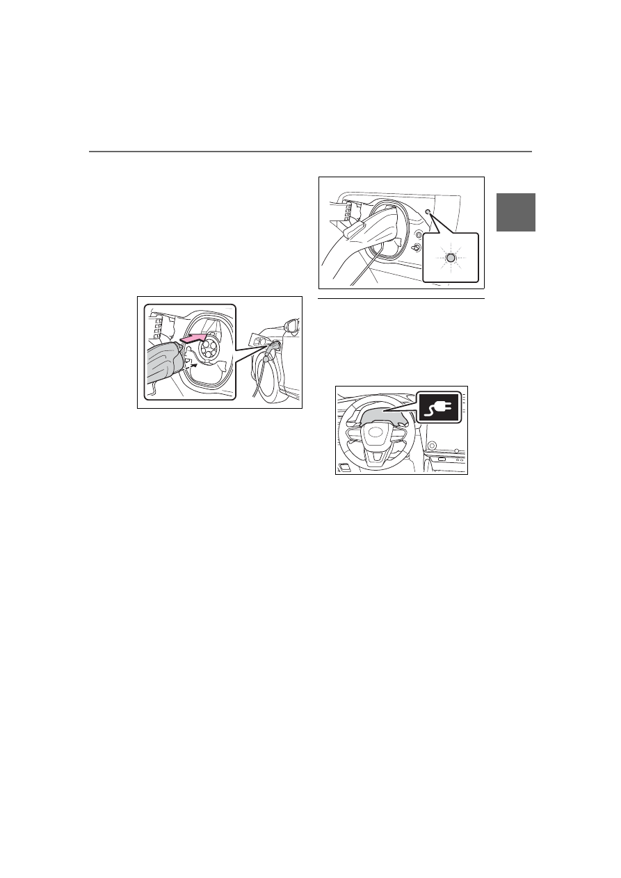
Insert the charging connector into 
the AC charging inlet.

Align the guide position on the bottom of 

the charging connector, and push the 

charging connector straight into the AC 

charging inlet as far as possible. Once a 

click sound is heard, check that the 

charging connector is securely locked.
When the charging connector is inserted 

straight as far as possible, it will automati-

cally lock. (

P.39)

6

Confirm that the charging indicator 
of the charging port is illuminated.

Charging will not start if the charging indi-

cator does not illuminate when the 

charging connector is inserted. (

P.535)

If the charging indicator is flashing, the 

charging schedule is registered. (

P.51)

If the error warning indicator on the CCID 

(Charging Circuit Interrupting Device) 

flashes during charging, check P.541and 

follow the correction procedure.
The charging indicator will turn off when 

charging is completed.
The charging indicator will also turn off 

when charging is interrupted. In this case, 

refer to P.534

When connecting the AC charging con-

nector

If the door is opened or the power switch is 

turned to ON with the AC charging con-

nector connected, the charging cable indi-

cator turns on to notify that the AC 

charging connector is connected.

If the charging indicator of the charging 

port flashes after connecting the AC 

charging cable

The charging schedule (

P.60) is regis-

tered and charging cannot be performed. 

To cancel charging using the charging 

schedule and start charging, perform any of 

the following procedures.

Turn “Charge Now” on (

P.63, 64)

While the charging indicator is flashing, 

remove and reconnect the charging con-

nector immediately

When the charging connector cannot 

be inserted into the AC charging inlet

P.40

Safety function

If the latch release button is pressed, 

charging will not begin even if the AC 

charging cable is connected.
Also, charging will be stopped if the latch 

52

1-3. Charging with the EV system

release button is pressed and held for sev-

eral seconds during charging. When 

restarting charging, reinsert the charging 

connector after pulling it out, and check 

that the charging indicator of the charging 

port illuminates.

Charging time may increase

P.48

When your circuit breaker trips during 

charging

The upper limit of the charging current can 

be changed on the center display as fol-
lows.

*1, 2

 (

P.597)

Max

16A

8A

The maximum charging current is limited to 
less than or equal to the selected current.

*3

If the breaker still trips while charging, even 

after changing the upper limit of the 

charging current, check if the connected 

power source meets the specified charging 

conditions. (

P.41)

*1

: The maximum charging current cannot 

be changed when the power switch is in 
ACC.

*2

: If the power supply of the AC charging 

stand being used has been adjusted or 
depending on the AC charging cable 
being used, the supplied current may be 
lower than the set maximum charging 
current.

*3

: Restricting the charging current will 

lengthen the charging time.

Changing the “Charging Limit” settings

The upper limit of the charge capacity can 

be changed on the center display as fol-
lows.

*

 (

P.597)

Full

90%

80%

70%

60%

50%

The selected upper limit value is common to 

AC charging and DC charging.
If the setting is changed during DC 

charging, charging may stop due to the 

operation of the DC charger timer and the 

traction battery cannot be fully charged.

*

: The charging limit settings cannot be 

changed when the power switch is in 
ACC.

Protection function of AC charging inlet 

overheating

By installing a temperature sensor to the 

AC charging inlet, prevents parts from 

melting when the temperature rises due to 

foreign matter entering the charging con-

nector.
When a certain temperature increase is 

detected, charging is stopped immediately.
After this, when a door is opened while the 

power switch is off, a message will be dis-

played on the multi-information display 

(

P.483)

WARNING

When charging

Observe the following precautions.

Failure to do so may cause an unex-

pected accident, resulting in death or 

serious injury.

Connect to a power source suitable 

for charging. (

P.41)

Check that the AC charging cable, 

plug and socket are free of foreign 

matter.

Before charging, check that the AC 

charging inlet is not deformed, dam-

aged or corroded, and check that the 

inlet is free of foreign matter such as 

dirt, snow and ice.

If there is dirt or dust in these areas, 

remove completely before inserting 

the charging connector.

53

1-3. Charging with the EV system

1

Be

fore
 driving

WARNING

Do not get the terminals of the AC 

charging inlet wet.

Only use sockets where the plug can 

be securely inserted.

Do not bundle or wind the AC 

charging cable while charging, as 

doing so may result in overheating.

Do not touch the terminals of the 

charging connector and AC charging 

inlet with a sharp metal objects (nee-

dles, etc.,) or hands, or short them with 

foreign objects.

When charging outdoors, make sure 

to connect to a weatherproof socket 

for outdoor use.

Ensure the weatherproof socket cover 

closes completely. If the weatherproof 

socket cover cannot be closed, install a 

weatherproof socket cover that will 

close.

In order to stop charging at the 

charging station, follow the instruc-

tions of the charger.

If any heat, smoke, odors, noise or 

other abnormalities are noticed during 

charging, stop charging immediately.

Do not insert the plug if the socket is 

submerged in water or snow.

When charging while it is raining or 

snowing, do not connect or disconnect 

the plug if your hands are wet. Also, do 

not get the plug or socket wet.

Do not charge the vehicle during a 

lightning storm.

Prevent the AC charging cable from 

being caught in the door or back door.

Do not let the wheels on the AC 

charging cable, plug, charging con-

nector and CCID (Charging Circuit 

Interrupting Device).

Firmly insert the plug into the socket.

Do not use an extension cord and con-

verting adaptor.

Close the hood before using the 

charging system.

The cooling fan may start operating 

suddenly. Touching or getting close to 

rotating parts such as the fan may 

cause your hands or clothes (espe-

cially a necktie or scarf) to become 

caught and result in a serious injury.

After connecting the charging cable, 

confirm that it is not wound around 

anything.

If the power indicator on the CCID 

(Charging Circuit Interrupting 

Device) does not illuminate after plug-

ging the AC charging cable into the 

socket, unplug it immediately.

If the error warning indicator on the 

CCID (Charging Circuit Interrupting 

Device) illuminates or flashes during 

charging

There may be an electrical leakage in the 

power source path, or there may be a 

malfunction in the AC charging cable or 

CCID (Charging Circuit Interrupting 

Device).

Refer to P.541and follow the correction 

procedure. If the error warning indicator 

does not turn off even after performing 

the correction procedure, immediately 

stop charging, remove the AC charging 

cable and contact your Lexus dealer. 

Continuing to charge the vehicle in that 

condition may lead to unforeseen acci-

dents or serious injury.

Onboard traction battery charger

The onboard traction battery charger is 

located in the motor compartment. 

Make sure to observe the following pre-

cautions regarding the onboard traction 

battery charger. Failure to observe these 

precautions may result in death or seri-

ous injury such as burns and electric 

shocks.

54

1-3. Charging with the EV system

1

Unlock the doors to unlock the 
charging connector. (

P.39)

The charging connector will be unlocked 

and the charging inlet light will illuminate 

when the doors are unlocked.

2

Pull the charging connector 
towards you while pressing the 
latch release button.

If the latch release button is pressed during 

charging (while the charging indicator is 

illuminated), charging will be interrupted.

3

Attach the charging connector cap.

4

Close the charging port lid.

5

Remove the plug from the socket 
when the charging equipment will 
not be used for a prolonged period 
of time.

Hold the body of the plug when removing.
Make sure to put the cable away immedi-

ately after disconnecting. (

P.35)

When leaving the plug inserted, inspect 

the plug and connector once a month to 

WARNING

The onboard traction battery charger 

is hot during charging. Do not touch 

the onboard traction battery charger, 

as doing so may result in burns.

Do not disassemble, repair or modify 

the onboard traction battery charger. 

When the onboard traction battery 

charger needs to be repaired, consult 

your Lexus dealer.

NOTICE

When charging

Do not insert the plug into the AC 

charging inlet.

The AC charging inlet may be damaged.

Using private power generator

Do not use private power generators as a 

power source for charging.

Doing so may make charging unstable, 

the voltage may be insufficient, and the 

charging operation may stop.

Charging station

Due to the environment in which the 

power equipment is located, charging 

may be unstable due to noise, the voltage 

may be insufficient, and the charging 

operation may stop.

After charging

55

1-3. Charging with the EV system

1

Be

fore
 driving

check if dirt or dust has accumulated.

When the outside temperature is low or 

high

The level shown on the SOC (State of 

Charge) gauge (

P.241) may drop slightly 

when the power switch is turned to ON, 

even if charging has been completed and 

the traction battery is fully charged. How-

ever, this does not indicate a malfunction.

When removing the charging connec-

tor

Press the latch release button, check that 

the lever raises up, and then pull the 

charging connector towards you.
If the lever does not raise up even after the 

latch release button is pressed, the charging 

connector is locked. If this occurs, unlock 

the doors using the smart access system 

with push-button start or wireless remote 

control to unlock the charging connector. 

(

P.92)

If the charging connector cannot be 

unlocked

P.540

WARNING

After charging

Remove the plug if it will not be used for a 

long time.

Dirt and dust may accumulate plug or 

socket, which could cause a malfunction 

or fire, possibly leading to death or seri-

ous injury.

NOTICE

After charging

Store the AC charging cable out of 

reach from infants and children.

After removing the plug from the 

socket, keep it in a safe place free from 

moisture and dust. 

The AC charging cable or plug may be 

damaged if the cable is stepped on or 

ridden over by the vehicle.

After disconnecting the charging con-

nector from the AC charging inlet, 

make sure to close the charging port 

lid.

If the charging port lid is left open, 

water or foreign objects may enter the 

AC charging inlet, which could lead to 

vehicle damage.

56

1-3. Charging with the EV system

P.47

1

Open the charging port lid. 
(

P.32)

The charging inlet light will illuminate.

2

Open the DC charging inlet cap.

3

Insert DC charging connector 
firmly and fully into the charging 
inlet

Insert the DC charging connector and it 

will lock automatically.
The DC charging connector shape and 

treatment will differ depending on the type 

of DC charger. Perform the operations in 

accordance to handling procedures of the 

DC charger.

4

Operate the DC charger and start 
the charging.

Follow the handling procedures of the DC 

charger to start charging.
Charging starts after a system check is 

done.
Stop the charging in accordance to the 

handling procedures of the DC charger 

when it is desired to interrupt the DC 

charging.

When connecting the DC charging 

connector

If the door is opened or the power switch is 

How to use DC charging

This section explains the DC 
charging procedure for the trac-
tion battery.

When using a DC charger, make 
sure to check the operation 
instructions of the DC charger.

WARNING

When using a DC charger

Observe the following precautions.

Failure to do so may cause an unex-

pected accident, resulting in death or 

serious injury.

Use a SAE J 1772 compliant DC char-

ger.

Do not use the charging cable longer 

than 30 meters.

Confirm the following before 
charging

When charging

57

1-3. Charging with the EV system

1

Be

fore
 driving

turned to ON with the DC charging con-

nector connected, the charging cable indi-

cator turns on to notify that the DC 

charging connector is connected.

Charging time may increase when

P.48

When the DC charging connector can-

not be inserted into the DC charging 

inlet

P.40

If a message indicating vehicle error on 

the DC charger side is displayed

Even if a message indicating vehicle error 

on the DC charger side (ex. vehicle error 

found, vehicle error occurred, etc.) is dis-

played, there is no vehicle fault but possibly 

a communication error between the DC 

charger and vehicle. In this case, there may 

be terminal damage (bad contact) in the 

DC charging connector. If there is no error 

with the vehicle, contact the facility man-

ager of the DC charger.

During DC charging

The current charging condition can be 

checked on the multi-information display.

The actual charging time may differ from 

that displayed on the DC charger during 

charging.

There may be occasions the radio cannot 

be heard due to noise occurrence during 

DC charging

As the battery approaches full charge, 

the charging speed will decrease and it 

will take longer to complete charging.

The time to complete charging may 

change, or charging may stop before 

reaching the upper limit of the charge 

capacity, due to the remaining charge of 

the traction battery, the outside tempera-

ture, the specifications of the charger 

(stand), etc.

It is recommended to avoid frequent DC 

charging to prevent a decline in the trac-

tion battery capacity.

Quickly move from the DC charging 

space for other users after the DC 

charging is completed.

Depending on the specifications of DC 

charger used, charging may be stopped 

before fully charged.

If DC charging is performed while the 

traction battery is extremely cold, such as 

in cold weather, steam may come out of 

the motor compartment or dew may be 

formed on the hood. This is because the 

heat, generated while the traction battery 

is warmed, causes snow, ice, or frost to 

evaporate. This is not a malfunction.

How to set the DC charging power

You can change the DC charging power 
limit on the center display.

*

 (

P.597)

*

: The settings cannot be changed when 

the power switch is in ACC.

Max

125kW

100kW

75kW

50kW

The maximum power when charging is lim-

ited to the selected power or less.
If Max is selected, the vehicle will be 

charged with the maximum power that can 

be charged.

Changing the “Charging Limit” settings

P.52

If “Check Charging System Close 

Charging Port Lid See Owner’s Man-

ual” is displayed on the multi-informa-

tion display

P.492

58

1-3. Charging with the EV system

1

Operate the DC charger to stop 
the charging.

WARNING

Warnings for DC charging

Be sure to observe the following when 

using DC charging.

Failure to do so may cause an accident 

that could lead to death or serious injury.

Check that the DC charger and DC 

charging inlet are not damaged. If 

there is any damage to the DC 

charging inlet, do not perform a DC 

charge and have it inspected immedi-

ately at your Lexus dealer.

Do not touch the terminals of the DC 

charging connector or inlet with 

metallic sharp tips (wires and needles), 

or allow a short circuit to occur with 

foreign objects.

Do not insert anything other than the 

DC charging connector into the DC 

charging inlet.

Check that the DC charging cable is 

not coiled up or pinned underneath 

heavy objects.

Be sure the DC charging inlet makes 

direct contact with the DC charging 

connector.

Do not connect conversion adapters, 

extension cords, etc., between the DC 

charging connector and DC charging 

inlet.

When DC charging is interrupted, fol-

low the handling procedures of the 

DC charger. Immediately stop the DC 

charging when there is an outbreak of 

heat, smoke, strange noises or smells, 

etc., during charging.

Check that the DC charging connec-

tor and DC charging inlet do not have 

foreign objects or snow or ice 

attached to it. If anything is attached to 

the inlet, be sure to completely remove 

the material before connecting the DC 

charging connector.

Do not charge the vehicle when there 

is a possibility of lightning. If you notice 

lightning while charging the vehicle, do 

not touch the vehicle and the DC 

charging cable.

Do not get the DC charging inlet ter-

minals wet.

Close the hood when using DC 

charging. The cooling fan may sud-

denly start to run. Keep hands and 

clothing (especially a tie, a scarf or a 

muffler) away from the fan. Failure to 

do so may cause the hands or clothing 

to be caught, resulting in serious injury.

When connecting the DC charging 

connector

Follow the handling procedures of the 

DC charger to connect the DC charging 

connector. If the connector is not con-

nected properly, the system cannot rec-

ognize the connection, and it may be 

possible to start the EV system.

After charging is completed, make sure 

to remove the DC charging connector 

from the DC charging inlet before start-

ing the EV system.

If the vehicle is started off with the con-
nector still connected, it could lead to an 
accident, possibly resulting in death or 
serious injury.

NOTICE

When using DC charging

Make sure to follow the handling proce-

dures of the DC charger. If the proce-

dures are not followed properly, the 

vehicle and the DC charger may be 

damaged.

After charging

59

1-3. Charging with the EV system

1

Be

fore
 driving

DC charging connector will be unlocked 

automatically when charging is completed.

2

Remove the DC charging connec-
tor.

The DC charging connector shape and 

treatment will differ depending on the type 

of DC charger. Perform the operations in 

accordance to handling procedures of the 

DC charger.
Return the removed DC charging connec-

tor to its original position.

3

Close the DC charging inlet cap, 
and then close the charging port 
lid.

When DC charging cannot be stopped

If charging cannot be stopped from the DC 

charger side due to a malfunction, etc.
You can also stop DC charging by pressing 

the door unlock button (on the electronic 

key, or driver’s door) three times at 1 to 2 

seconds intervals.

If the DC charging connector cannot be 

unlocked

P.540

After DC charging

Even if the traction battery is charged to the 

upper limit value that is set, the level of 

charge displayed on the DC charger may 

be lower than the actual one.

NOTICE

Caution after DC charging

Be sure to attach the DC charging inlet 

cap to the DC charging inlet and then 

close the charging port lid after remov-

ing the DC charging connector from the 

inlet. If the DC charging inlet cap or 

charging port lid is not closed, foreign 

materials may get into the inlet and the 

EV system may be malfunctioning.

60

1-3. Charging with the EV system

Calendar settings

The current date and time is automatically 

set using GPS. However, if the automatic 

setting of the clock is turned off on the cen-

ter display, it will be necessary to manually 

set the date and time. For details, refer to 

the “MULTIMEDIA OWNER’S MAN-

UAL”.
If the calendar settings check screen is dis-

played when an attempt was made to regis-

ter a charge schedule, check that the 

correct date is set. If it is incorrect, be sure 

to correct it.
If the calendar information is wrong, the 

charging schedule function will not operate 

normally.

When registering the charging sched-
ule, the following settings can be 
changed.

Select the charging mode

One of the two following charging 
modes can be selected.

“Start at set time”

Starts charging at the set time

*

 and fin-

ishes charging when fully charged.

“Start and stop at set times”

AC charging is performed according 
to the set start time and stop time.

*

*

: There might be a slight error in the tim-

ing when charging starts due to the state 
of the traction battery.

Repeated setting

The periodic charging schedule can be 
set by selecting your desired day of the 
week. Select one or more day of the 
week to do the charging schedule.

Turning “Charge Now” on and off

To start charging without changing the 
charging schedule setting, turn 
“Charge Now” on to temporarily can-
cel the charging schedule and enable 
charging after connecting the AC 
charging connector.

*

*

: If the charging connector is removed 

during charging while the charging 
schedule is registered and “Charge 
Now” is on, “Charge Now” turns off.

“Next charging event”

Of the registered charging schedules, 
the closest charging schedule after the 
current time is called the “Next 
charging event”.
For charging schedule, AC charging 
will be performed according to the 
Next charging event.

The charging schedule can be regis-
tered on the center display. (

P.61)

Charging schedule

The charging schedule cannot be set 

while driving.

A maximum of 15 charging schedules 

can be registered.

If the charging mode is set to “Start and stop 

Using the charging schedule 
function

AC charging can be carried out at 
the desired time by registering the 
charging schedule.

Settings of the charging sched-
ule function

Registering the charging sched-
ule

61

1-3. Charging with the EV system

1

Be

fore
 driving

at set times” and the start time and stop time 

are set to the same time, charging will be 

performed for 24 hours from the start time.
The charging schedule function cannot be 

used when using DC charging.

To make sure that the charging schedule 

function operates correctly

Check the following items.

Adjust the clock to the correct time

*

The calendar is set to the correct date

*

Check that the power switch is turned off

After registering the charging schedule, 

connect the AC charging connector

The charging start time is determined 
based on the charging schedule at the time 
that the AC charging connector was con-
nected.

Connect the AC charging connector 

before the start time

When the charging mode is set to “Start at 
set time”, if you connect the AC charging 
connector after the set start time, the next 
charging schedule will be referenced.
When the charging mode is “Start and stop 
at set times”, if you connect the AC 
charging connector after the start time, 
charging will start immediately and 
charging will be performed until the stop 
time.

After connecting the AC charging con-

nector, check that the charging indicator 

of the charging port flashes (

P.49)

Do not use an socket that has a power cut 

off function (including a timer function)

Use an socket that constantly supplies 
electricity. For sockets where the power is 
cut off due to a timer function, etc., 
charging may not be carried out according 
to plan if the power is cut off during the set 
time.

*

: For the setting procedure for the clock 

and calendar, refer to “MULTIMEDIA 
OWNER’S MANUAL”.

When the AC charging connector 

remains connected to the vehicle

When the charging mode is set to “Start 

at set time”, even if multiple consecutive 

charging schedules are registered, the 

next charge will not be carried out 

according to the charging schedule until 

the AC charging connector is removed 

and reconnected after charging com-

pletes. Also, when the traction battery is 

fully charged, charging according to the 

charging schedule will not be carried out.

If the charging stop time is reached 

before the traction battery is fully 

charged and the charging mode is set to 

“Start and stop at set times”, the nearest 

charging schedule after the stop time is 

updated as the next charging schedule, 

and charging is repeated until the battery 

is fully charged.

Smartphone-linked operation

It may be necessary to use a smartphone 

with a dedicated app to change the 

charging settings.

When charging schedules are ignored

When the following operations are per-

formed while the charging schedule is on 

standby, charging schedule is temporarily 

canceled and charging is started.

When turning My Room Mode on 

(

P.65)

When turning “Charge Now” on 

(

P.63, 64)

When an operation that temporarily can-

cel charging using the charging schedule 

(

P.51)

Battery heater (

P.43)/Battery 

Cooler (

P.43)

Depending on the temperature of the trac-

tion battery, the traction battery heater or 

traction battery cooler may be activated 

and the charging indicator may light up 

while the timer is waiting for charging.

Setting operations related to the 

Setting operations on center dis-
play

62

1-3. Charging with the EV system

charging schedule are performed on 
the charging schedule screen.

Displaying the charging schedule 
screen

1

With the power switch in ON, 
select 

 on the center display.

Charging schedule settings cannot be 

changed when the power switch is in ACC.

2

Select “Charging schedule”.

How to read the charging schedule 
screen

Charging schedules

Displays the week-long registered 
charging schedule in a list using icons.

“Add” switch

Select to add a new item to the charging 
schedule. (

P.62)

“Edit” switch

Select to change or delete registered items 
on the charging schedule. (

P.63)

“Charge now” switch

Each time the button is selected, “Charge 
now” switches between on and off. 
(

P.62)

Registering the charging schedule

1

Display the “Charging schedule” 
screen. (

P.62)

2

Select “Add”.

The “Add event” screen will be displayed 

on the screen.

3

Change the schedule to the 
desired time.

Charging mode

Select “Start at set time” or “Start and stop 
at set times” to set the desired charging 
mode.
• When “Start at set time” is selected
Set the charging start time, and select 
“OK”.
• When “Start and stop at set times” is 

selected

Set the charging start time and stop time, 
and select “OK”.

Repeated settings

Select the day of the week and select 
“OK”.
When turned on, the charging schedule is 
repeated on that day. It is possible to turn 
more than one day on.

4

After setting operations are com-
plete, press “Save”.

The charging schedule is registered 
and an icon is added to the schedule.
To cancel registration of the charging 
schedule, select 

.

After setting operations are complete, 
when the power switch is turned off 
and the AC charging connector is con-
nected to the vehicle, charging is car-
ried out according to the charging 
schedule settings.

Switching charging schedules 
between on and off

1

Display the charging schedule 
screen. (

P.62)

2

Press “Edit”.

The “Events” screen will be displayed on 

A

B

C

D

63

1-3. Charging with the EV system

1

Be

fore
 driving

the screen.

3

From the items displayed on the 

screen, select 

 or 


in the row of the charging schedule 
you wish to change.

If the charging schedule you wish to 
change is not displayed on the screen, 
scroll the list up and down to display it.
Each time the button is pressed, the 
charging schedule switches between 
on and off.

Changing the registered charging 
schedules

1

Display the “Charging schedule” 
screen. (

P.62)

2

Press “Edit”.

The “Events” screen will be displayed on 

the screen.

3

Press “Edit” on the “Events” screen.

4

From the items displayed on the 
screen, press the charging sched-
ule you wish to change.

Changing registered items:

Change the desired settings as described 
in step 

3

 to step 

4

 of the “Registering 

the charging schedule” procedure. 

(

P.62)

When a setting is changed, its icon on the 
calendar also changes.

Deleting registered items:

Select “Delete”.
A deletion confirmation message will be 
displayed.
Press “Delete” to delete the selected 
charging schedule.
To cancel deletion, press “Cancel” or the 

return button.
When a charging schedule is deleted, its 
icon is also deleted from the calendar.

Turning “Charge now” on

1

Display the charging schedule 
screen. (

P.62)

2

Select 

 of “Charge now”.

Each time the button is pressed, 
“Charge now” switches between on 
and off.
After setting operations are complete, 
charging starts when the AC charging 
connector is connected.

Changing Next Event

If the customize content “ACC custom-
ize” is not set to OFF, the ending 
screen will not be displayed. If it is this 
case, check the settings on the center 
display. (

P.597)

Turn the power switch off.
Next event will be displayed according 
to the charging schedule settings.

When press “OK”, close Next 
charging event screen.

When press “Charge Now”, charge 
now is turned on.

When all charging schedules are turned 

off

The icon is not displayed on the charging 

schedule screen.
The icon will be displayed by turning it ON 

on the “Events” screen.

When charging schedule setting opera-

tions are canceled

When the vehicle is in the following condi-

tions, charging schedule setting operations 

64

1-3. Charging with the EV system

are canceled.

The power switch is turned off before the 

settings are confirmed

The vehicle starts off

A display with a higher priority than that 

of the charging schedule setting is shown

“Next charging event”

After charging completes, the “Next 

charging event” on the display will not 

change until the AC charging cable is 

removed, after charging is performed 

according to the “Next charging event”.

Setting “Charge Now” to on

1

Turn the power switch off.

The closing display screen is displayed on 

the multi-information display.

(If the door is opened while waiting for 

charging schedule, the same screen will be 

displayed.)

2

Vehicles without a head-up display: 
Press 

 of the meter control 

switch.

*1

Vehicles with a head-up display: 
Press the steering wheel switch at 
the position where “YES” is dis-
played on the multi-information dis-
play.

After setting operations are complete, 
charging starts when the AC charging 
connector is connected.

*1

: Each time 

 is pressed, “Charge 

now” will turn on/off.

When the power switch is turned off

When the power switch is turned off, the 

charging schedule (next scheduled 

charging) will be displayed on the closing 

display and the registered details can be 
checked.

*2

*2

: The closing display screen may not be 

displayed during charging.

NOTICE

While performing the setting opera-

tion

When performing the setting operation 

while the EV system is stopped, be care-

ful that the 12-volt battery will not be dis-

charged.

Setting operations on 
multi-information display

NOTICE

While performing the setting opera-

tion

When performing the setting operation 

while the EV system is stopped, be care-

ful that the 12-volt battery will not be dis-

charged.

65

1-3. Charging with the EV system

1

Be

fore
 driving

1

Connect the charge cable to the 
vehicle to start charging.

AC Charging: 

P.49

DC Charging: 

P.56

2

Turn the power switch to ON while 
charging.

My Room Mode settings is automatically 

displayed on the center display.

3

Select “Yes”.

My Room Mode is started and it is possible 

to use the air conditioning system, audio 

system, etc.
When not using My Room Mode, select 

“No”.
To disable My Room Mode, turn the power 

switch off.
My Room Mode will automatically be off 

when DC charging is completed.

Meter display while charging

After turning the power switch to ON while 

charging, the power switch automatically 

turns off if My Room Mode is not selected 

within approximately 100 seconds.

When using My Room Mode the follow-

ing may occur

When the remaining charge of the trac-

tion battery drops to the lower limit, the 

air conditioning system automatically 

stops. In that case, the air conditioning 

system cannot operate until the remain-

ing charge of the traction battery 

increases. Turn off the power switch once, 

then use My Room Mode after the 

remaining charge of the traction battery 

increases.

The charging time of the traction battery 

gets longer.

Noise may be heard from the radio 

depending on conditions of the radio 

wave.

The surrounding area of the onboard 

traction battery charger in the motor 

compartment may become hot.

The electric power steering system warn-

ing light (yellow) may turn on, but this is 

not a malfunction.

Using My Room Mode during DC 

charging

When using My Room mode during DC 

charging, the amount of charge at the time 

of charge completion will be lower than 

when not using it.
In addition, when DC charging in an envi-

ronment with low outside temperatures and 

high humidity, the air conditioner prioritizes 

dehumidification of the vehicle interior. This 

may lead to even lower charge at the time 

of completion.
When prioritizing the amount of charge, 

turn off the cooling and dehumidification 

functions. (

P.181, 204)

When a charging schedule is registered

When My Room Mode starts while the 

charging schedule is on standby, charging 

schedules are ignored and charging starts.

Using My Room Mode

When the charging cable is con-
nected to the vehicle, electrical 
components such as the air condi-
tioning system and audio system 
can be used by the power supply 
from an external power source.

Starting My Room Mode

WARNING

Warnings for using My Room Mode

Observe the following precautions.

Failure to do so may result in death or a 

serious health hazard.

66

1-3. Charging with the EV system

WARNING

Do not leave children, people who 

need care, or pets inside the vehicle. 

The temperature inside the vehicle 

may become high or low due to fea-

tures such as the automatic shut-off. 

The children, people who need care, 

or pets left inside the vehicle may suf-

fer heatstroke dehydration or hypo-

thermia. Also, since the wipers, etc., 

can be operated, there may be acci-

dental operation, possibly leading to 

an accident.

Use the mode after sufficiently check-

ing the vicinity of the vehicle for safety 

hazards.

67

1-4. Vehicle load limits

1

Be

fore
 driving

1-4.Vehicle load limits

Total load capacity (vehicle capac-
ity weight) (

P.564)

Total load capacity means the com-
bined weight of occupants, cargo and 
luggage.

Seating capacity (

P.564)

Seating capacity means the maximum 
number of occupants whose esti-
mated average weight is 150 lb. (68 
kg) per person.

TWR (Trailer Weight Rating)

Lexus does not recommend towing a 
trailer with your vehicle.

Cargo capacity

Cargo capacity may increase or 
decrease depending on the weight and 
the number of occupants.

Total load capacity and seating capacity

These details are also described on the tire 

and loading information label.

Vehicle load limits

Vehicle load limits include total 
load capacity, seating capacity, 
towing capacity and cargo capac-
ity.

Vehicle load limit terminology 
and definitions

WARNING

Do not overload the vehicle. It may not 

only cause damage to the tires, but also 

degrade steering and braking ability, 

resulting in an accident.

68

1-5. For safe driving with children on board

1-5.For safe driving with children on board

1

Unlock

2

Lock

These locks can be set to prevent children 
from opening the rear doors. Push down 
on each rear door switch to lock both rear 
doors.

Door opening method when using a 

child-protector lock

Unlock the door and press the door opener 

switch of the door handle and open the 

door. If it is necessary to open the door from 

inside the vehicle, open the rear side win-

dow and press the door opener switch of 

the door handle and open the door.

Riding with children

Observe the following precautions 
when children are in the vehicle.
Use a child restraint system appro-
priate for the child, until the child 
becomes large enough to properly 
wear the vehicle’s seat belt.

It is recommended that children 
sit in the rear seats to avoid acci-
dental contact with the rotary 
shifter, wiper switch, etc.

Use the rear door child-protector 
lock or the window lock switch to 
avoid children opening the door 
while driving or operating the 
power window accidentally. 
(

P.68, 100)

Do not let small children operate 
equipment which may catch or 
pinch body parts, such as the 
power window, hood, back door, 
seats etc.

WARNING

When children are in the vehicle

Never leave children unattended in the 

vehicle, and never allow children to have 

or use the key.

Children may be able to start the vehicle 

or shift the vehicle into neutral. There is 

also a danger that children may injure 

themselves by playing with the windows, 

or other features of the vehicle. In addi-

tion, heat build-up or extremely cold 

temperatures inside the vehicle can be 

fatal to children.

Preventing the rear doors from 
being opened from the inside of 
the vehicle (child-protector 
lock)

The door cannot be opened from 
inside the vehicle when the lock is 
set.

69

1-5. For safe driving with children on board

1

Be

fore
 driving

Points to remember: P.69
Child restraint system: P.70
When using a child restraint system: 
P.71
Child restraint system installation 
method
• Fixed with a seat belt: P.73
• Fixed with a child restraint LATCH 

anchor: P.77

• Using an anchor bracket (for top 

tether strap): P.79

The laws of all 50 states of the U.S.A. 
as well as Canada now require the use 
of child restraint systems.

Prioritize and observe the warn-
ings, as well as the laws and regula-

tions for child restraint systems.

Use a child restraint system until the 
child becomes large enough to 
properly wear the vehicle’s seat belt.

Choose a child restraint system that 
suits your vehicle and is appropriate 
to the age and size of the child.

Child restraint systems

Before installing a child restraint 
system in the vehicle, there are pre-
cautions that need to be observed, 
different types of child restraint sys-
tems, as well as installation meth-
ods, etc., written in this manual.

Use a child restraint system when 
riding with a small child that cannot 
properly use a seat belt. For the 
child’s safety, install the child restraint 
system to a rear seat. Be sure to fol-
low the installation method that is in 
the operation manual enclosed with 
the restraint system.

Table of contents

Points to remember

WARNING

When a child is riding

Observe the following precautions.

Failure to do so may result in death or 

serious injury.

For effective protection in automobile 

accidents and sudden stops, a child 

must be properly restrained, using a 

seat belt or child restraint system 

which is correctly installed. For installa-

tion details, refer to the operation man-

ual enclosed with the child restraint 

system. General installation instruction 

is provided in this manual.

Lexus strongly urges the use of a 

proper child restraint system that con-

forms to the weight and size of the 

child, installed on the rear seat. 

According to accident statistics, the 

child is safer when properly restrained 

in the rear seat than in the front seat.

Holding a child in your or someone 

else’s arms is not a substitute for a child 

restraint system. In an accident, the 

child can be crushed against the wind-

shield or between the holder and the 

interior of the vehicle.

Handling the child restraint system

If the child restraint system is not prop-

erly fixed in place, the child or other pas-

sengers may be seriously injured or even 

killed in the event of sudden braking, sud-

den swerving, or an accident.

70

1-5. For safe driving with children on board

Types of child restraint system installation methods

Confirm with the operation manual enclosed with the child restraint system about 
the installation of the child restraint system.

WARNING

If the vehicle were to receive a strong 

impact from an accident, etc., it is pos-

sible that the child restraint system has 

damage that is not readily visible. In 

such cases, do not reuse the restraint 

system.

Make sure you have complied with all 

installation instructions provided with 

the child restraint system manufac-

turer and that the system is properly 

secured.

Keep the child restraint system prop-

erly secured on the seat even if it is not 

in use. Do not store the child restraint 

system unsecured in the passenger 

compartment.

If it is necessary to detach the child 

restraint system, remove it from the 

vehicle or store it securely in the lug-

gage compartment.

Child restraint system

71

1-5. For safe driving with children on board

1

Be

fore
 driving

When installing a child restraint 
system to a front passenger seat

For the safety of a child, install child 
restraint systems to a rear seats. When 
installing child restraint system to a 
front passenger seat is unavoidable, 
adjust the seat as follows and install the 
child restraint system.

Move the seat fully rearward.

Move the seat height to the upper 
most position.

Adjust the seatback angle to the 
most upright position.

If there is a gap between the child seat and 
the seatback, adjust the seatback angle 
until good contact is achieved.

If the head restraint interferes with 
your child restraint system, and the 
head restraint can be removed, 

Installation method

Page

Seat belt attachment

P.73

Child restraint LATCH 

anchors attachment

P.77

Anchor brackets (for top 

tether strap) attachment

P.79

When using a child restraint sys-
tem

72

1-5. For safe driving with children on board

remove the head restraint.

Otherwise, put the head restraint in the 
upper most position.

WARNING

When using a child restraint system

Observe the following precautions.

Failure to do so may result in death or 

serious injury.

Never install a rear-facing child 

restraint system on the front passenger 

seat even if the “AIR BAG OFF” indi-

cator light is illuminated. In the event of 

an accident, the force of the rapid infla-

tion of the front passenger airbag can 

cause death or serious injury to the 

child if the rear-facing child restraint 

system is installed on the front passen-

ger seat.

A forward-facing child restraint system 

may be installed on the front passen-

ger seat only when it is unavoidable. A 

child restraint system that requires a 

top tether strap should not be used in 

the front passenger seat since there is 

no top tether strap anchor for the front 

passenger seat.

A forward-facing child restraint system 

may be installed on the front passen-

ger seat only when it is unavoidable. 

When installing a forward-facing child 

restraint system on the front passenger 

seat, raise the seatback as much as 

possible, move the seat to the rear-

most position, and raise the seat to the 

highest position, even if the “AIR BAG 

OFF” indicator light is illuminated.

If the head restraint interferes with the 
installation of the child restraint system, 
and the head restraint can be removed, 
remove the head restraint.
If the head restraint cannot be removed, 
raise it to the uppermost position.

Do not allow the child to lean his/her 

head or any part of his/her body 

against the door or the area of the seat, 

front or rear pillars, or roof side rails 

from which the SRS side airbags or 

SRS curtain shield airbags deploy even 

if the child is seated in the child 

restraint system. It is dangerous if the 

SRS side airbags and curtain shield air-

bags inflate, and the impact could 

cause death or serious injury to the 

child.

73

1-5. For safe driving with children on board

1

Be

fore
 driving

A child restraint system for a small 
child or baby must itself be properly 
restrained on the seat with the lap por-
tion of the lap/shoulder belt.

Installing child restraint system 
using a seat belt (child restraint 
lock function belt)

Install the child restraint system in 
accordance to the operation manual 
enclosed with the child restraint sys-
tem.

Rear-facing 

 Infant seat/con-

vertible seat

1

Adjust the rear seat.

If there is a gap between the child seat and 

the seatback, adjust the seatback angle 

until good contact is achieved.

2

Place the child restraint system on 
the rear seat facing the rear of the 
vehicle.

3

Run the seat belt through the child 
restraint system and insert the plate 
into the buckle. Make sure that the 
belt is not twisted.

4

Fully extend the shoulder belt and 
allow it to retract to put it in lock 

WARNING

When a booster seat is installed, 

always ensure that the shoulder belt is 

positioned across the center of the 

child’s shoulder. The belt should be 

kept away from the child’s neck, but 

not so that it could fall off the child’s 

shoulder.

Use child restraint system suitable to 

the age and size of the child and install 

it to the rear seat.

If the driver’s seat interferes with the 

child restraint system and prevents it 

from being attached correctly, attach 

the child restraint system to the 

right-hand rear seat.

Adjust the front passenger seat so that 

it does not interfere with the child 

restraint system.

Child restraint system fixed with 
a seat belt

74

1-5. For safe driving with children on board

mode. In lock mode, the belt cannot 
be extended.

5

While pushing the child restraint 
system down into the rear seat, 
allow the shoulder belt to retract 
until the child restraint system is 
securely in place.

After the shoulder belt has retracted to a 

point where there is no slack in the belt, 

pull the belt to check that it cannot be 

extended.

6

After installing the child restraint 
system, rock it back and forth to 
ensure that it is installed securely. 
(

P.76)

Forward-facing 

 Convertible 

seat

1

Adjust the seat.

When using the front passenger 
seat

If installing the child restraint system to the 
front passenger seat is unavoidable, refer 

to P.71for the front passenger seat adjust-
ment.

When using the rear seat

If there is a gap between the child seat and 
the seatback, adjust the seatback angle 
until good contact is achieved.

2

Remove the head restraint if it inter-
feres with your child restraint sys-
tem. (

P.121)

If the head restraint cannot be removed, 

raise it to the uppermost position.

3

Place the child restraint system on 
the seat facing the front of the vehi-
cle.

4

Run the seat belt through the child 
restraint system and insert the plate 

75

1-5. For safe driving with children on board

1

Be

fore
 driving

into the buckle. Make sure that the 
belt is not twisted.

5

Fully extend the shoulder belt and 
allow it to retract to put it in lock 
mode. In lock mode, the belt cannot 
be extended.

6

While pushing the child restraint 
system into the rear seat, allow the 
shoulder belt to retract until the 
child restraint system is securely in 
place.

After the shoulder belt has retracted to a 

point where there is no slack in the belt, 

pull the belt to check that it cannot be 

extended.

7

If the child restraint has a top tether 
strap, follow the child restraint man-
ufacturer’s operation manual 
regarding the installation, using the 
top tether strap to latch onto the 
top tether strap anchor. (

P.79)

8

After installing the child restraint 
system, rock it back and forth to 
ensure that it is installed securely. 
(

P.76)

Booster seat

1

If installing the child restraint sys-
tem to the front passenger seat is 
unavoidable, refer to P.71for the 
front passenger seat adjustment.

2

High back type: Remove the head 
restraint if it interferes with your 
child restraint system. (

P.121)

If the head restraint cannot be removed, 

raise it to the uppermost position.

3

Place the child restraint system on 
the seat facing the front of the vehi-
cle.

76

1-5. For safe driving with children on board

Booster type

High back type

4

Sit the child in the child restraint 
system. Fit the seat belt to the child 
restraint system according to the 
manufacturer’s instructions and 
insert the plate into the buckle. 
Make sure that the belt is not 
twisted.

Check that the shoulder belt is correctly 

positioned over the child’s shoulder and 

that the lap belt is as low as possible. 

(

P.123)

Removing a child restraint system 
installed with a seat belt

Press the buckle release button and 
fully retract the seat belt.

When releasing the buckle, the child 
restraint system may spring up due to the 
rebound of the seat cushion. Release the 
buckle while holding down the child 
restraint system.
Since the seat belt automatically reels itself, 
slowly return it to the stowing position.

WARNING

When installing a child restraint sys-

tem

Observe the following precautions.

Failure to do so may result in death or 

serious injury.

Do not allow children to play with the 

seat belt. If the seat belt becomes 

twisted around a child’s neck, it may 

lead to choking or other serious inju-

ries that could result in death.

If this occurs and the buckle cannot be 

unfastened, scissors should be used to 

cut the belt.

Ensure that the belt and plate are 

securely locked and the seat belt is not 

twisted.

Shake the child restraint system left 

and right, and forward and backward 

to ensure that it has been securely 

installed.

77

1-5. For safe driving with children on board

1

Be

fore
 driving

Child restraint LATCH anchors

LATCH anchors are provided for the 
outboard rear seats. (Tags displaying 
the location of the anchors are 
attached to the seats.)

When installing in the rear out-
board seats

Install the child restraint system in 
accordance to the operation manual 
enclosed with the child restraint sys-
tem.

1

Adjust the seat.

If there is a gap between the child seat and 

the seatback, adjust the seatback angle 

until good contact is achieved.

2

Remove the head restraint if it inter-
feres with your child restraint sys-
tem. (

P.121)

If the head restraint cannot be removed, 

WARNING

When a booster seat is installed, 

always ensure that the shoulder belt is 

positioned across the center of the 

child’s shoulder. The belt should be 

kept away from the child’s neck, but 

not so that it could fall off the child’s 

shoulder.

Follow all installation instructions pro-

vided by the child restraint system 

manufacturer.

When securing some types of child 

restraint systems in rear seats, it may 

not be possible to properly use the 

seat belts in positions next to the child 

restraint without interfering with it or 

affecting seat belt effectiveness. Be 

sure your seat belt fits snugly across 

your shoulder and low on your hips. If it 

does not, or if it interferes with the 

child restraint, move to a different posi-

tion. Failure to do so may result in 

death or serious injury.

When installing a child restraint system 

in the rear center seat, adjust both seat 

cushions to the same position and 

align both seatbacks at the same 

angle. The seatbacks must be adjusted 

to the same angle. Otherwise, the 

child restraint system cannot be 

securely restrained and this may cause 

death or serious injuries in the event of 

sudden braking, sudden swerving or 

an accident.

If the seat is adjusted, reconfirm the 

security of the child restraint system.

When installing a booster seat

To prevent the belt from going into ALR 

lock mode, do not fully extend the shoul-

der belt. ALR mode causes the belt to 

tighten only. This could cause injury or 

discomfort to the child. (

P.125)

Do not use a seat belt extender

If a seat belt extender is used when 

installing a child restraint system, the seat 

belt will not securely hold the child 

restraint system, which could cause 

death or serious injury to the child or 

other passengers in the event of sudden 

braking, sudden swerving or an accident.

Child restraint system fixed with 
a child restraint LATCH anchor

78

1-5. For safe driving with children on board

raise it to the uppermost position.

3

Widen the gap between the seat 
cushion and seatback slightly.

With flexible lower attachments

4

Latch the hooks of the lower 
attachments onto the LATCH 
anchors.
For owners in Canada: 
The symbol on a child restraint sys-
tem indicates   the presence of a 
lower connector system.

Canada only

With rigid lower attachments

4

Latch the buckles onto the LATCH 
anchors.
For owners in Canada: 
The symbol on a child restraint sys-
tem indicates   the presence of a 
lower connector system.

Canada only

5

If the child restraint has a top tether 
strap, follow the child restraint man-
ufacturer’s operation manual 
regarding the installation, using the 
top tether strap to latch onto the 
top tether strap anchor. (

P.79)

6

After installing the child restraint 
system, rock it back and forth to 
ensure that it is installed securely. 
(

P.76)

When installing in the rear center 
seat

There are no LATCH anchors behind 
the rear center seat. However, the 

A

A

A

A

79

1-5. For safe driving with children on board

1

Be

fore
 driving

inboard LATCH anchors of the out-
board seats, which are 16.5 in. (420 
mm) apart, can be used if the child 
restraint system manufacturer’s 
instructions permit use of those 
anchors with the anchor spacing 
stated.
Child restraint systems with rigid lower 
attachments cannot be installed in the 
center seat. This type of child restraint 
system can only be installed in the out-
board seat.

Laws and regulations pertaining to 

anchors

The LATCH system conforms to 

FMVSS225 or CMVSS210.2.

Child restraint systems conforming to 

FMVSS213 or CMVSS213 specifications 

can be used.

This vehicle is designed to conform to SAE 

J1819.

Anchor brackets (for top tether 
strap)

Anchor brackets are provided for each 
rear seat.
Use anchor brackets when fixing the 
top tether strap.

Outboard rear seats

WARNING

When installing a child restraint sys-

tem

Observe the following precautions.

Failure to do so may result in death or 

serious injury.

When using the LATCH anchors, be 

sure that there are no foreign objects 

around the anchors and that the seat 

belt is not caught behind the child 

restraint system.

Follow all installation instructions pro-

vided by the child restraint system 

manufacturer.

Never attach two child restraint system 

attachments to the same anchor. In a 

collision, one anchor may not be 

strong enough to hold two child 

restraint system attachments and may 

break.

If the LATCH anchors are already in 

use, use the seat belt to install a child 

restraint system in the center seat.

When securing some types of child 

restraint systems in rear seats, it may 

not be possible to properly use the 

seat belts in positions next to the child 

restraint without interfering with it or 

affecting seat belt effectiveness. Be 

sure your seat belt fits snugly across 

your shoulder and low on your hips. If it 

does not, or if it interferes with the 

child restraint, move to a different posi-

tion. Failure to do so may result in 

death or serious injury.

If the seat is adjusted, reconfirm the 

security of the child restraint system.

Using an anchor bracket (for top 
tether strap)

80

1-5. For safe driving with children on board

Anchor brackets
Top tether strap

Rear center seat

Anchor bracket
Top tether strap

Fixing the top tether strap to the 
anchor bracket

Install the child restraint system in 
accordance to the operation manual 
enclosed with the child restraint sys-
tem.

1

Remove the head restraint if it inter-
feres with your child restraint sys-
tem. (

P.121)

If the head restraint cannot be removed, 

raise it to the uppermost position.

2

Latch the hook onto the anchor 
bracket and tighten the top tether 
strap.

Make sure the top tether strap is securely 

latched. (

P.76)

When installing the child restraint system 

with the head restraint being raised, be 

sure to have the top tether strap pass 

underneath the head restraint.

Outboard rear seats

Hook
Top tether strap

Rear center seat

Hook
Top tether strap

Laws and regulations pertaining to 

anchors

The LATCH system conforms to 

FMVSS225 or CMVSS210.2. 

Child restraint systems conforming to 

FMVSS213 or CMVSS213 specifications 

can be used. 

This vehicle is designed to conform to SAE 

J1819.

A
B

A
B

A
B

A
B

81

1-5. For safe driving with children on board

1

Be

fore
 driving

WARNING

When installing a child restraint sys-

tem

Observe the following precautions. 

Failure to do so may result in death or 

serious injury.

Firmly attach the top tether strap and 

make sure that the belt is not twisted.

Do not attach the top strap to anything 

other than the anchor bracket.

Follow all installation instructions pro-

vided by the child restraint system 

manufacturer.

When installing the child restraint sys-

tem with the head restraint being 

raised, after the head restraint has 

been raised and then the anchor 

bracket has been fixed, do not lower 

the head restraint.

When installing a child restraint system 

in the rear center seat, adjust both seat 

cushions to the same position and 

align both seatbacks at the same 

angle. The seatbacks must be adjusted 

to the same angle. Otherwise, the 

child restraint system cannot be 

securely restrained and this may cause 

death or serious injuries in the event of 

sudden braking, sudden swerving or 

an accident.

If the seat is adjusted, reconfirm the 

security of the child restraint system.

82

1-6. Entering/exiting the vehicle

1-6.Entering/exiting the vehicle

The following keys are provided with 
the vehicle.

Electronic keys

• Operating the smart access system with 

push-button start (

P.84)

• Operating the wireless remote control 

function (

P.93)

Mechanical keys
Key number plate
Card key (electronic key) (if 
equipped)

Operating the smart access system with 
push-button start (

P.84)

Key types

NOTICE

To prevent key damage

Observe the following precautions

Do not drop the keys, subject them to 

strong shocks or bend them.

Do not expose the keys to high tem-

peratures for long periods of time.

Do not get the keys wet or wash them 

in an ultrasonic washer, etc.

A

B
C
D

Do not attach metallic or magnetic 

materials to the keys or place the keys 

close to such materials.

Do not disassemble the keys.

Do not attach a sticker or anything else 

to the surface of the electronic key.

Do not place the keys near objects that 

produce magnetic fields, such as TVs, 

audio systems and induction cookers.

Do not place the keys near medical 

electrical equipment such as low-fre-

quency therapy equipment or micro-

wave therapy equipment, and do not 

receive medical attention with the keys 

on your person.

Carrying the electronic key on your 

person

Carry the electronic key 3.9 in. (10 cm) 

or more away from electric appliances 

that are turned on. Radio waves emitted 

from electric appliances within 3.9 in. (10 

cm) of the electronic key may interfere 

with the key, causing the key to not func-

tion properly.

Handling the card key

If the battery or card key terminals get 

wet, the battery may corrode and the 

card key may stop working.If the key is 

dropped into water, or if drinking 

water, etc., is spilled on the key, imme-

diately remove the battery cover and 

wipe the battery and terminals. (To 

remove the battery cover, lightly grasp 

and pull it.) If the battery is corroded, 

have your Lexus dealer replace the 

battery.

Do not crush the battery cover or use 

a screwdriver to remove the battery 

cover. Forcibly removing the battery 

cover may bend or damage the key.

If the battery cover is frequently 

removed, the battery cover may 

become loose.


Content      ..      1      2      3      ..