Lexus RX500h (2023 year). Manual in english - page 3
 

  Index      Manuals     Lexus RX500h (2023 year). Manual in english


Search            copyright infringement  


Content      ..     1      2      3      4      ..


Lexus RX500h (2023 year). Manual in english - page 3


89

2-1. Instrument cluster

2

Vehi

cle

 status 

inform

ati

on a

nd i

ndic
ators

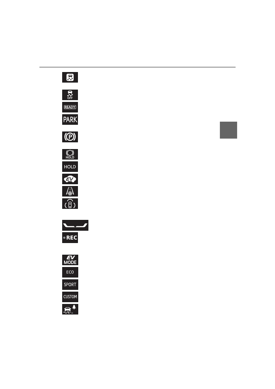
Drive mode indicators

*1

: These lights come on when the power 

switch is turned to ON to indicate that a 
system check is being performed. They 
will turn off after the hybrid system is 
started, or after a few seconds. There 
may be a malfunction in a system if the 
lights do not come on, or turn off. Have 
the vehicle inspected by your Lexus 
dealer.

*2

: This light comes on when the system is 

turned off.

*3

: This light illuminates on the outside rear 

view mirrors.

*4

: When the outside temperature is 

approximately 37°F (3°C) or lower, this 
indicator will flash for approximately 10 
seconds, then stay on.

*5

: This light comes on when the stop lights 

are illuminated by the operation of the 
brake pedal or the driving assist system.

(flashes)

Slip indicator

*1

 (

P.395)

VSC OFF indicator

*1, 2


(

P.395)

“READY” indicator (

P.208)

(U.S.A.)

Parking brake indicator 
(

P.226)

(Canada)

Parking brake indicator 
(

P.226)

Brake hold standby indicator

*1


(

P.229)

Brake hold operated indicator

*1


(

P.229)

EV indicator (

P.74)

Low outside temperature indi-
cator

*4

 (

P.90)

(green/whit

e)

PDA indicator (

P.289)

Stop light indicator

*5

REC indicator (

P.317)

EV drive mode indicator 
(RX350h only) (

P.212)

Eco drive mode indicator 
(

P.390)

Sport mode indicator 
(

P.390)

Customize mode indicator 
(

P.390)

Trail Mode indicator (

P.392)

90

2-1. Instrument cluster

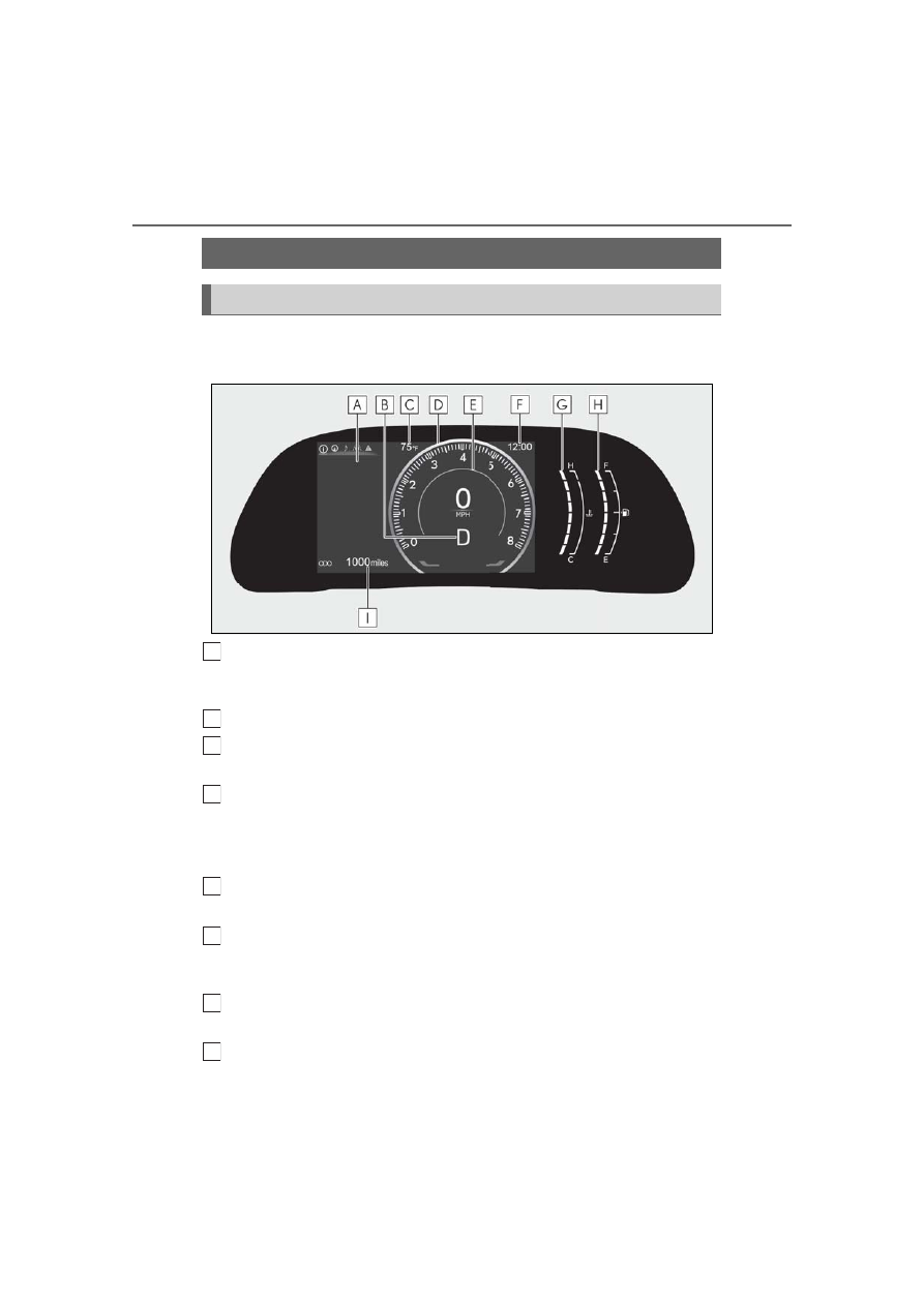
Locations of gauges and meters (except F SPORT models)

Vehicles without a head-up display

Multi-information display

Presents the driver with a variety of vehicle data and displays warning messages if a mal-
function occurs. (

P.98, 526)

Shift position/shift range
Outside temperature

Displays the ambient temperature within the range of -40°F (-40°C) to 140°F (60°C).

Tachometer/Hybrid System Indicator/Speedometer

Tachometer: Displays the engine speed in revolutions per minute.
Hybrid System Indicator: Displays hybrid system output or regeneration level. (

P.95)

Depending on the selected drive mode or certain settings, the display will change.

Background color of driving mode

Background color changes according to the driving mode.

Clock

Automatically adjusts the time by using the GPS time information (GPS clock). For details, 
refer to the “MULTIMEDIA OWNER’S MANUAL”.

Engine coolant temperature gauge

Displays the engine coolant temperature.

Fuel gauge

Gauges and meters

Meter display

A

B
C

D

E

F

G

H

91

2-1. Instrument cluster

2

Vehi

cle

 status 

inform

ati

on a

nd i

ndic
ators

Displays the quantity of fuel remaining in the tank.

Odometer and trip meter display (

P.96)

Vehicles with a head-up display

Engine coolant temperature gauge

Displays the engine coolant temperature.

Outside temperature

Displays the ambient temperature within the range of -40°F (-40°C) to 140°F (60°C).

Tachometer/Hybrid System Indicator/Analog speedometer

Tachometer: Displays the engine speed in revolutions per minute.
Hybrid System Indicator: Displays hybrid system output or regeneration level. (

P.95)

Depending on the selected drive mode or certain settings, the display will change.

Digital speedometer
Shift position/shift range
Clock

Automatically adjusts the time by using the GPS time information (GPS clock). For details, 
refer to the “MULTIMEDIA OWNER’S MANUAL”.

Navigation system estimated time of arrival display (if equipped)

Displays the estimated time of arrival according to the navigation system.

Fuel gauge

Displays the quantity of fuel remaining in the tank.

Distance to empty

Displays the driving range with remaining fuel.

Multi-information display

Presents the driver with a variety of vehicle data and displays warning messages if a mal-

I

A

B

C

D

E
F

G

H

I

J

92

2-1. Instrument cluster

function occurs. (

P.98, 526)

Background color of driving mode

Background color changes according to the driving mode.

Odometer and trip meter display (

P.96)

Locations of gauges and meters (F SPORT models)

Depending on the shift position or current drive mode, the meter displays or posi-
tion of some gauges will change.

Ring display state

Engine coolant temperature gauge

Displays the engine coolant temperature.

Outside temperature

Displays the ambient temperature within the range of -40°F (-40°C) to 140°F (60°C).

Tachometer/Hybrid System Indicator/Analog speedometer

Tachometer: Displays the engine speed in revolutions per minute.
• Rev indicator
• Rev  peak
Hybrid System Indicator: Displays hybrid system output or regeneration level. (

P.95)

Depending on the selected drive mode or certain settings, the display will change.

Digital speedometer
Shift position/shift range/gear position
Clock

Automatically adjusts the time by using the GPS time information (GPS clock). For details, 
refer to the “MULTIMEDIA OWNER’S MANUAL”.

Navigation system estimated time of arrival display (if equipped)

K

L

A

B

C

D

E
F

G

93

2-1. Instrument cluster

2

Vehi

cle

 status 

inform

ati

on a

nd i

ndic
ators

Displays the estimated time of arrival according to the navigation system.

Fuel gauge

Displays the quantity of fuel remaining in the tank.

Distance to empty

Displays the driving range with remaining fuel.

Multi-information display

Presents the driver with a variety of vehicle data and displays warning messages if a mal-
function occurs. (

P.98, 526)

Background color of driving mode

Background color changes according to the driving mode.

Odometer and trip meter display (

P.96)

Bar display state

Engine coolant temperature gauge

Displays the engine coolant temperature.

Outside temperature

Displays the ambient temperature within the range of -40°F (-40°C) to 140°F (60°C).

Tachometer/Hybrid System Indicator

Tachometer: Displays the engine speed in revolutions per minute.
• Rev indicator
• Rev  peak
Hybrid System Indicator: Displays hybrid system output or regeneration level. (

P.95)

Depending on the selected drive mode or certain settings, the display will change.

Shift position/shift range/gear position/digital speedometer
Clock

H

I

J

K

L

A

B

C

D

E

94

2-1. Instrument cluster

Automatically adjusts the time by using the GPS time information (GPS clock). For details, 
refer to the “MULTIMEDIA OWNER’S MANUAL”.

Navigation system estimated time of arrival display (if equipped)

Displays the estimated time of arrival according to the navigation system.

Fuel gauge

Displays the quantity of fuel remaining in the tank.

Distance to empty

Displays the driving range with remaining fuel.

Multi-information display

Presents the driver with a variety of vehicle data and displays warning messages if a mal-
function occurs. (

P.98, 526)

Background color of driving mode

Background color changes according to the driving mode.

Odometer and trip meter display (

P.96)

Rev indicator (F SPORT models)

When the engine speed reaches a set 
speed or the red zone, the tachometer 
will be highlighted.

The indicators will be displayed in amber 
when the engine speed reaches a set 
speed, and in red when the engine speed 
reaches the red zone.
The engine speed at which the Rev indica-
tor is displayed can be changed on the 
center display. (

P.590)

Ring display state

Bar display state

Rev peak (F SPORT models)

When the engine speed reaches or 
exceeds 4000 rpm, an afterimage of 
the tachometer will be displayed at the 
highest engine speed for approxi-
mately 1 second.

F

G

H

I

J

K

95

2-1. Instrument cluster

2

Vehi

cle

 status 

inform

ati

on a

nd i

ndic
ators

Ring display state

Bar display state

The meters and display illuminate when

The power switch is in ON.

Hybrid System Indicator

This illustration is for explanation only and 

may differ depending on the specifications 

of the vehicle.

Charge area

Shows regeneration

*

 status.

Eco area

Shows that the vehicle is being driven in an 
Eco-friendly manner.

Power area

Shows that an Eco-friendly driving range is 
being exceeded (during full power driving 
etc.)

Hybrid Eco area

Shows that gasoline engine power is not 
being used very often.
The gasoline engine will automatically stop 
and restart under various conditions.

By keeping the indicator needle within 

Eco area, more Eco-friendly driving can 

be achieved.

Charge area indicates regeneration

*

 sta-

tus. Regenerated energy will be used to 

charge the hybrid battery (traction bat-

tery).

*

: When used in this manual, regeneration 

refers to the conversion of energy cre-
ated by the movement of the vehicle into 
electrical energy.

Engine speed

On hybrid electric vehicles, engine speed is 

precisely controlled in order to help 

improve fuel efficiency and reduce exhaust 

emissions etc.

There are times when the engine speed that 

is displayed may differ even when vehicle 

operation and driving conditions are the 

same.

Outside temperature display

In the following situations, the correct 

outside temperature may not be dis-

played, or the display may take longer 

than normal to change:

• When stopped, or driving at low speeds 

(less than 12 mph [20 km/h])

• When the outside temperature has 

changed suddenly (at the entrance/exit of 

a garage, tunnel, etc.)

When “--” or “E” is displayed, the system 

may be malfunctioning. Take your vehicle 

to your Lexus dealer.

Distance to empty

This distance is computed based on your 

average fuel consumption. As a result, 

the actual distance that can be driven 

may differ from that displayed.

A

B

C

D

96

2-1. Instrument cluster

When only a small amount of fuel is 

added to the tank, the display may not be 

updated. When refueling, turn the power 

switch off. If the vehicle is refueled with-

out turning the power switch off, the dis-

play may not be updated.

Liquid crystal display

Small spots or light spots may appear on the 

display. This phenomenon is characteristic 

of liquid crystal displays, and there is no 

problem continuing to use the display.

Free/Open Source Software Informa-

tion

This product contains Free/Open Source 

Software (FOSS). The license information 

and/or the source code of such FOSS can 

be found at the following URL.
https://www.denso.com/global/en/

opensource/meter/toyota/

Display items

Odometer

Displays the total distance the vehicle has 
been driven.

Trip meter A/trip meter B

Displays the distance the vehicle has been 
driven since the meter was last reset. Trip 
meters A and B can be used to record and 
display different distances independently.

Distance until next engine oil 
change

Displays the distance the vehicle can be 
driven until an oil change is necessary.

Changing the display

Each time the “ODO TRIP” switch is 
pressed, the displayed item will be 
changed. When the trip meter is dis-
played, pressing and holding the switch 
will reset the trip meter.

WARNING

The information display at low tem-

peratures

Allow the interior of the vehicle to warm 

up before using the liquid crystal infor-

mation display. At extremely low tem-

peratures, the information display 

monitor may respond slowly, and display 

changes may be delayed.

For example, there is a lag between the 

driver’s shifting and the new gear number 

appearing on the display. This lag could 

cause the driver to downshift again, 

causing rapid and excessive engine brak-

ing and possibly an accident resulting in 

death or injury.

NOTICE

To prevent damage to the engine and 

its components

Do not let the indicator needle of the 

tachometer enter the red zone, which 

indicates the maximum engine speed.

The engine may be overheating if the 

engine coolant temperature gauge is 

in the red zone (H); or “Engine Cool-

ant Temp High Stop in a Safe Place 

See Owner’s Manual” is shown on the 

multiinformation display. In this case, 

immediately stop the vehicle in a safe 

place, and check the engine after it has 

cooled completely. (

P.560)

Odometer and trip meter dis-
play

97

2-1. Instrument cluster

2

Vehi

cle

 status 

inform

ati

on a

nd i

ndic
ators

Depending on the current drive mode 
or settings, the displays will change as 
follows. Settings can be changed on 
the center display. (

P.590)

Vehicles without a head-up display

Tachometer

The tachometer will be displayed in the fol-
lowing situations when the meter display 
type setting is set to display type 1 or dis-
play type 3.
• When the tachometer setting is set to 

always display the tachometer

• When the tachometer setting is set to 

change according to the driving mode 
and sport mode is selected

Hybrid System Indicator

The hybrid system indicator will be dis-
played in the following situations when the 
meter display type setting is set to display 
type 1 or display type 3.
• When the tachometer setting is set to 

always display the hybrid system indica-
tor

• When the tachometer setting is set to 

change according to the driving mode 
and a driving mode other than sport 
mode is selected

Speedometer

Always displayed.
The display will change between a digital 
speedometer and/or analog speedometer 
depending on the meter display type set-
ting.

Vehicles with a head-up display

Tachometer

Displayed when the meter display type set-
ting is set to display type 1.
F SPORT models: Also displayed in the fol-
lowing situations when the setting is set to 
display type 3.
• When the tachometer setting is set to 

always display the tachometer

• When the tachometer setting is set to 

change according to the driving mode 
and sport mode is selected

Hybrid System Indicator

Displayed when the meter display type set-
ting is set to display type 1.
F SPORT models: Also displayed in the fol-
lowing situations when the setting is set to 
display type 3.
• When the tachometer setting is set to 

always display the hybrid system indica-
tor

• When the tachometer setting is set to 

change according to the driving mode 
and a driving mode other than sport 
mode is selected

Speedometer

A digital speedometer is always displayed.
When the meter display type setting is set 
to display type 2, an analog speedometer 
will also be displayed.

The brightness of the instrument panel 
lights can be adjusted.

Changing between the tachom-
eter/hybrid system indica-
tor/speedometer displays

Changing the instrument panel 
light brightness

98

2-1. Instrument cluster

1

Darker

2

Brighter

Brightness of the meters (day mode and 

night mode)

The brightness of the meters is changed 

between day mode and night mode.

Day mode: When the tail lights are off or 

when the tail lights are on but the sur-

rounding area is bright

Night mode: When the tail lights are on 

and the surrounding area is dark

When the tail lights are on but the sur-

rounding area is bright, any adjustments 

made to the meter brightness levels will be 

applied to both modes at once.

Display area

A variety of driving-related information 
can be displayed. Depending on the 
situation, warning or advice pop-up 
displays will also be displayed.

Vehicles without a head-up display

Content display area
Driving support system informa-
tion display area

When a menu icon other than 

 is 

selected, if the driving support system 
operates, the system operating state will be 
displayed.

Vehicles with a head-up display

Navigation system-linked display 
area (if equipped)

Multi-information display

Displayed contents summary

A
B

A

99

2-1. Instrument cluster

2

Vehi

cle

 status 

inform

ati

on 

an

indic
ators

If the navigation system linked-display is 
not displayed in the content display area, 
route guidance will be displayed.

Driving support system informa-
tion display area

When driving support system information 
is not displayed in the content display area, 
if the driving support system operates, the 
system operating state will be displayed.

Content display area

Items displayed in the content dis-
play area

Vehicles without a head-up display

By selecting menu icons on the 
multi-information display, the following 
items can be displayed.

Vehicles with a head-up display

The following items can be displayed.

Drive information 1

Drive information 2

Energy monitor/EV driving ratio

Audio system-linked display

Navigation system-linked display (if 
equipped)

*

RX500h: Boost gauge/engine oil 
temperature gauge/engine oil pres-

sure gauge

G-force

RX500h: Gear Position

Driving support system information 
display

*

Blank (No items)

*

: Displayed on the head-up display when 

the display mode is set to display the 
maximum.

Liquid crystal display

P.96

Driving information display

Navigation system-linked dis-
play (if equipped)

Audio system-linked display

Driving support system infor-
mation display

Warning message

B

C

WARNING

Caution for use while driving

When operating the multi-information 

display while driving, pay extra atten-

tion to the safety of the area around the 

vehicle.

Do not look continuously at the 

multi-information display while driving 

as you may fail to see pedestrians, 

objects on the road, etc. ahead of the 

vehicle.

The information display at low tem-

peratures

P.96

Cautions during setting up the dis-

play

As the hybrid system needs to be operat-

ing during setting up the display, ensure 

that the vehicle is parked in a place with 

adequate ventilation. In a closed area 

such as a garage, exhaust gases includ-

ing harmful carbon monoxide (CO) may 

collect and enter the vehicle. This may 

lead to death or a serious health hazard.

100

2-1. Instrument cluster

NOTICE

While setting up the display

To prevent 12-volt battery discharge, 

ensure that the hybrid system is operat-

ing while setting up the display features.

101

2-1. Instrument cluster

2

Vehi

cle

 status 

inform

ati

on a

nd i

ndic
ators

*

: If  equipped

The content displayed will differ according to the driving conditions and display 
mode of the head-up display. Depending on the situation, pop-up displays will also 
be displayed.

Main display area

Displays the following items:
• Driving support system information display
• Hybrid System Indicator/Tachometer
• Compass (if equipped)
• Speed limit of the current road (linked to the navigation system) (U.S.A. only)

Driving information display area

Displays the following items:
• Speedometer
• Shift position/shift range/gear position

: Master warning icon

Displayed when a warning message is displayed.

Head-up display will operate when

The power switch is in ON.

Head-up display

The head-up display may seem dark or hard 

to see when viewed through sunglasses, 

especially polarized sunglasses. Adjust the 

Head-up display

*

The head-up display projects a variety of driving-related information and the 
operating state of the driving support systems on the windshield.

System components

A

B

C

102

2-1. Instrument cluster

brightness of the head-up display or 

remove your sunglasses.

The tachometer/hybrid system indica-

tor is displayed when

When the following conditions are met, the 

tachometer or hybrid system indicator will 

be displayed on the head-up display.

The head-up display is set to display the 

maximum. (

P.590)

LTA (Lane Tracing Assist) is disabled. 

(

P.274)

LDA (Lane Departure Alert) is disabled. 

(

P.590)

The cruise control, selected by pressing 

the driving assist mode select switch, is 

canceled. (

P.307, 308)

1

Select 

 on the center display.

2

Select “Vehicle customize”.

3

Select “Head up display”.

The following settings for the head-up dis-

play can be changed. (

P.590)

Display on/off

Display mode

Height

Brightness

Angle

Changing settings with the steering 

wheel switches

If any of the following items have been set as 

as a favorite steering wheel switch function, 

settings of the head-up display can be 

changed using the steering wheel switches.

: Display on/off

: Display mode

/

: Height

/

: Brightness

Enabling/disabling of the head-up dis-

play

If the head-up display is disabled, it will 

remain disabled when the power switch is 

WARNING

Before using the head-up display

Check that the position and brightness 

of the head-up display image does not 

interfere with safe driving. Incorrect 

adjustment of the image’s position or 

brightness may obstruct the driver’s 

view and lead to an accident, resulting 

in death or serious injury.

Do not continuously look at the 

head-up display while driving as you 

may fail to see pedestrians, objects on 

the road, etc. ahead of the vehicle.

NOTICE

To prevent damage to components

Do not place any drinks near the 

head-up display projector. If the pro-

jector gets wet, electrical malfunctions 

may result.

Do not place anything on or put stick-

ers onto the head-up display projector. 

Doing so could interrupt head-up dis-

play indications.

Do not touch the inside of the head-up 

display projector or thrust sharp edges 

or the like into the projector. Doing so 

could cause mechanical malfunctions.

Changing settings of the 
head-up display

103

2-1. Instrument cluster

2

Vehi

cle

 status 

inform

ati

on 

an

indic
ators

turned off then back to ON.

Display brightness

In addition to the brightness setting, the 

brightness of the display will change auto-

matically according to the ambient bright-

ness.

Head-up display automatic position 

adjustment (vehicles with driving posi-

tion memory)

If the display position is recorded into mem-

ory, the head-up display will be automati-

cally adjusted to the desired position.

Vehicles without a head-up display

/

: Select menu icons

/

: Change displayed con-

tent, scroll up/down the screen and 
move the cursor up/down
Return to the previous screen
Start/receive call

Linked with the hands-free system, sending 
or receiving call is displayed. For details 
regarding the hands-free system, refer to 
the “MULTIMEDIA OWNER’S MAN-
UAL”.

Enter/Set

WARNING

Caution for changing settings of the 

head-up display

As the hybrid system needs to be operat-

ing while changing the settings of the 

head-up display, ensure that the vehicle 

is parked in a place with adequate venti-

lation. In a closed area such as a garage, 

exhaust gases including harmful carbon 

monoxide (CO) may collect and enter 

the vehicle. This may lead to death or a 

serious health hazard.

NOTICE

When changing the settings of the 

head-up display

To prevent 12-volt battery discharge, 

ensure that the hybrid system is operat-

ing while the changing the settings of the 

head-up display.

Displayed content

Components/Operations

A

B

C

D

104

2-1. Instrument cluster

Vehicles with a head-up display

Center display
Steering switch

The function of each switch differs depending on the conditions and settings.
When a switch is touched, the function of each switch is displayed on the head-up display. If 
the head-up display is off, or when it is not possible to display content on the head-up dis-
play, the functions will be displayed on the multi-information display.
Also, preferred functions for each switch can be set on the center display.

A
B

105

2-1. Instrument cluster

2

Vehi

cle

 status 

inform

ati

on a

nd i

ndic
ators

Switch function change switch

Each time this switch is pressed, the functions will change.

Switch icon display

The icon of each switch will be displayed. The touched switch will be highlighted. (

)

Switch function guide display

The function guide for the touched switch will be displayed.

Switching the display of the 
multi-information display (vehicles 
without a head-up display)

1

Press 

 or 

 of the meter con-

trol switch.

Switching driving information

1

Press the 

 or 

 meter control 

switch to select 

. Then press 


or .

Switching the display of the 
multi-information display (vehicles 
with a head-up display)

1

Select 

 on the center display.

2

Select “Vehicle customize”.

3

Select “Meter”.

4

Select 

 or 

 of “Display 

switching”.

The display changes each time the switch is 

selected.

If the steering wheel switches do not 

respond when touched (vehicles with a 

head-up display)

It is easier to make the steering wheel 

switches respond by moving your thumb 

while touching them.

If the surface of a steering wheel switch is 

dirty, turn the power switch off and then 

clean the switches.

By turning winter glove mode on, the sen-

sitivity of the switch sensors can be 

increased. (

P.590)

Switching with the steering wheel 

switches (vehicles with a head-up dis-

play)

If 

/

 is set as a favorite 

steering wheel switch function, the display 
can be switched by pushing 

 or 

.

Driving related information is dis-
played on the following displays.

Multi-information display

Head-up display (If equipped)

Center display

The items displayed will differ depend-
ing on the display.

The following items can be displayed 
on the multi-information display.
Use the displayed values as a refer-
ence only.

Current fuel consumption

Displays instantaneous current fuel con-
sumption

Average fuel consumption

C

D

F

E

Display of drive information

Drive information 1

106

2-1. Instrument cluster

The following items can be displayed 
on the multi-information display.

Average vehicle speed

Total driving time

The following items can be displayed 
on the multi-information display.

Distance to empty

Displays the driving range with remaining 
fuel.

Average fuel economy since start-
ing

Displays the average fuel consumption 
since starting.

Distance to empty

P.95

The energy monitor and EV driving 
ratio can be displayed on the 
multi-information display.
The energy monitor screen can be dis-
played on the center display.

Displaying Energy monitor screen 
on the center display

1

Select 

 on the main menu.

2

Select “Energy flow”.

Energy monitor

The energy monitor can be used to 

check the vehicle drive status, hybrid 
system operation status and energy 
regeneration status.
The arrows will appear in accordance 
with the energy flow. When there is no 
energy flow, arrows will not be dis-
played.
The color of the arrows will change as 
follows

Blue: When the hybrid battery (trac-
tion battery) is regenerated or 
charged.

Orange: When the hybrid battery 
(traction battery) is in use.

Red: When the gasoline engine is in 
use.

The image shows all the arrows as an 
example. The actual display will vary 
depending on conditions.

Multi-information display

Gasoline engine
Tires
Hybrid battery (traction battery)

This illustration is for explanation only and 
may differ depending on the specifications 
of the vehicle.

Drive information 2

Drive information 3 (vehicles 
without a head-up display)

Energy monitor/EV driving ratio 
(If equipped)

A
B
C

107

2-1. Instrument cluster

2

Vehi

cle

 status 

inform

ati

on a

nd i

ndic
ators

Center display

Gasoline engine
Front electric motor (traction 
motor)
Hybrid battery (traction battery)
Rear electric motor (traction 
motor)
Rear tires
Front tires

EV driving ratio since starting (If 
equipped)

Displays the percentage of EV driving 
since starting.
It is reset each time the hybrid system 
stops.

Color of the hybrid battery (traction 

battery) on the center display

It will be green when the hybrid battery 

(traction battery) is being charged, and yel-

low when the hybrid battery (traction bat-

tery) is being used.

Remaining charge amount warning of 

hybrid battery (traction battery)

The buzzer sounds intermittently when 

the hybrid battery (traction battery) 

remains without charging while the shift 

position is in N, or the remaining charge 

amount drops below a certain level. If the 

remaining charge amount drops further, 

the buzzer sounds continuously. 

(RX350h)

When a warning message is shown on 

the multi-information display and the 

buzzer sounds, follow the instructions 

displayed on the screen to perform trou-

bleshooting.

The following items can be displayed 
on the multi-information display.

Boost gauge

Displays the boost pressure. The display 
will change color if the specified pressure is 
exceeded.

Engine oil temperature gauge

Displays the engine oil temperature. The 
display will flash if the engine oil tempera-
ture exceeds 284 °F (140 °C).

Engine oil pressure gauge

Displays the engine oil pressure. A buzzer 
will sound and warning message will be 
displayed if the engine oil pressure 
becomes low. (

P.526)

This display is intended for use as a guide-
line. Depending on factors such as the road 
surface condition, temperature and vehicle 
speed, the display may not show the actual 
condition of the vehicle.

Displays lateral G-forces on the vehi-

A
B

C
D

E
F

Boost gauge/engine oil tempera-
ture gauge/engine oil pressure 
gauge (RX500h)

G-force

A

B

C

108

2-1. Instrument cluster

cle on the multi-information display.
Displays around the periphery of the 
G-force display, the left and right 
steering amount, accelerator pedal 
input, and brake fluid pressure.

Acceleration G-force on the vehi-
cle
Current G-force value (analyzed 
value of front/rear and left/right 
G-forces)
Record of the maximum G-forces
Accelerator pedal input
Brake fluid pressure
Left steering amount
Right steering amount

This display is intended for use as a guide-
line. Depending on factors such as the road 
surface condition, temperature and vehicle 
speed, the display may not show the actual 
condition of the vehicle.

Resetting the record of maximum 
G-forces

The display is reset each time the hybrid 
system is started.

Peak hold function

If lateral G-forces of 0.5 G or greater are 
generated, the G-force value display will 
turn amber and be held for 2 seconds.

G-force display

The G-force values may not be zero even 

when the vehicle is parked, such as when 

it is parked on an incline.

Depending on the vehicle usage condi-

tions, the brake fluid pressure display may 

not reach its maximum reading even 

though the brake pedal is fully depressed.

If a 12-volt battery terminal is discon-

nected and reconnected, the steering 

amount display may be disabled tempo-

rarily. After driving the vehicle for a while, 

the display will be enabled.

Displays the current shift range or gear 
position when the shift position is in D 
or M.

Displays no drive information contents 
on the multi-information display.

Fuel consumption information can be 
displayed on the center display.

Displaying fuel consumption/his-
tory screen on the center display

1

Select 

 on the main menu.

2

Select “Trip information”.

3

Select “Current” or “History”.

A

B

C
D

E
F

G

Gear Position (RX500h)

Blank (No items)

Current fuel consumption/his-
tory screen

109

2-1. Instrument cluster

2

Vehi

cle

 status 

inform

ati

on a

nd i

ndic
ators

Current fuel consumption screen

Resetting the history data
Fuel consumption in the past 15 
minutes
Current fuel consumption
Average vehicle speed since the 
hybrid system was started.
Trip range
Elapsed time since the hybrid sys-
tem was started.

Use the displayed average fuel consump-
tion as a reference. The image is an exam-
ple only, and may vary slightly from actual 
conditions.

History fuel consumption screen

Latest fuel consumption
Best recorded fuel consumption
Previous fuel consumption record
Resetting the history data
Updating the latest fuel consump-
tion data

Use the displayed average fuel consump-
tion as a reference. The image is an exam-
ple only, and may vary slightly from actual 
conditions.

Updating the history data

Update the latest fuel consumption by 

selecting “Update” to measure the current 

fuel consumption again.

Resetting the data

The fuel consumption data can be deleted 

by selecting “Clear data”.

Trip range

Displays the estimated maximum distance 

that can be driven with the quantity of fuel 

remaining.
This distance is computed based on your 

average fuel consumption. 

As a result, the actual distance that can be 

driven may differ from that displayed.

AWD operation status display can be 
displayed on the center display.

Displaying AWD operation status 
display on the center display

1

Select 

 on the main menu.

2

Select  “All wheel drive”.

AWD operation status

Torque distribution display: Displays 
the drive status of each wheel in 6 
steps from 0 to 5.
The illustration used is intended as an 
example, and may differ from the 
image that is actually displayed on the 
center display.

A
B

C
D

E
F

A
B
C
D

E

AWD operation status display

110

2-1. Instrument cluster

The tire pressure detected by the tire 
pressure warning system can be dis-
played on the center display.

Displaying the tire pressure on the 
center display

1

Select 

 on the main menu.

2

Select  “Tire pressure”.

Tire inflation pressure

P.486

The audio system-linked display dis-
plays the operating state of the audio 
system on the multi-information dis-
play.
Operations such as selecting the audio 
source or track, etc. can be performed.

The following information is displayed 
on the multi-information display.

Route guidance to destination

Speed limit of the current road 
(linked to the navigation system) 

(U.S.A. only)

Street name

Compass

Display position (vehicles with a 

head-up display)

Depending on the display settings of the 

head-up display, some content may be dis-

played on the head-up display and not in 

the content display area of the multi-infor-

mation display.

The operating state of the following 
systems can be displayed on the 
multi-information display or head-up 
display (if equipped).

Dynamic radar cruise control 
(

P.295)

Cruise control (

P.306)

LTA (Lane Tracing Assist) (

P.271)

LDA (Lane Departure Alert) 
(

P.279)

LCA (Lane Change Assist) (if 
equipped) (

P.276)

RSA (Road Sign Assist) (if 
equipped) (

P.293)

PDA (Proactive Driving Assist) 
(

P.285)

PCS (Pre-Collision System) 
(

P.261)

Display position (vehicles with a 

head-up display)

When the display mode of the head-up dis-

play is set to display the maximum, driving 

support system information will be dis-

played on the head-up display and not in 

Tire pressure

Audio system-linked display

Navigation system-linked dis-
play (if equipped)

Driving support system informa-
tion display

111

2-1. Instrument cluster

2

Vehi

cle

 status 

inform

ati

on a

nd i

ndic
ators

the content display area of the multi-infor-

mation display.

Pop-up displays will be displayed on 
the multi-information display or the 
head-up display (if equipped) when 
necessary.

When a pop-up display is displayed, a cur-
rent display may no longer be displayed. In 
this case, the display will return after the 
pop-up display disappears.

Driving support systems

Displays a warning/suggestion/advice 
message or the operating state of a rel-
evant system.

Dynamic radar cruise control

Cruise control

LTA (Lane Tracing Assist)

LDA (Lane Departure Alert)

LCA (Lane Change Assist) (if 
equipped)

PDA (Proactive Driving Assist)

PCS (Pre-Collision System)

RSA (Road Sign Assist) (if 
equipped)

SEA (Safe Exit Assist [with Door 
Opening Control])

FCTA (Front Cross Traffic Alert) (if 
equipped)

Warning message

Some warning messages are displayed 
when necessary, according to certain 
conditions.

Hands-free system status

Displayed when the hands-free system 
is operated.

Suggestion function

Displays suggestions to the driver in 
the following situations. To select a 
response to a displayed suggestion, 
use the steering switches.

Suggestion to enable the power 
back door

If the power back door system is disabled 
(setting on the center display set to off) and 
the power back door switch on the instru-
ment panel is operated, a suggestion mes-
sage will be displayed asking if you wish to 
enable the power back door system.
To enable the power back door system, 
select “YES”.
After enabling the power back door sys-
tem, press the power back door switch 
again to open or close the power back 
door.

Steering wheel switch operation 
display

Vehicles without a head-up display

Displayed when an audio remote con-
trol switch or a talk switch on the steer-
ing wheel is operated.

Vehicles with a head-up display

When a steering wheel switch is 
touched, the icon of each switch and a 
function guide is displayed.

Navigation system-linked informa-
tion (if equipped)

Depending on the situation, navigation 
system-linked route guidance to desti-
nation may be displayed.

Pop-up display information

112

2-1. Instrument cluster

The following items will be displayed 
on the multi-information display when 
the power switch is turned off.

Average fuel consumption since 
starting

*

Distance driven since starting

*

Driving time since starting

*

EV driving ratio since starting

*

Displays the percentage of EV driving 
since starting.

*

: It is reset each time the hybrid system 

stops.

Items displayed when the power 
switch is turned off

113

3

3

Be

fore
 dri
ving

Before driving

.

3-1. Key information

Keys ..................................................

114

Digital Key......................................

117

3-2. Opening, closing and locking the 

doors

Side doors ......................................

119

Power back door........................

124

Smart access system with 

push-button start.....................

139

3-3. Adjusting the seats

Front seats.....................................

144

Rear seats......................................

145

Head restraints............................

152

3-4. Adjusting the steering wheel and 

mirrors

Steering wheel.............................

155

Inside rear view mirror.............

156

Digital Rear-view Mirror.........

157

Outside rear view mirrors......

166

3-5. Opening, closing the windows 

and moon roof

Power windows...........................

169

Moon roof ......................................

171

Panoramic moon roof ..............

174

3-6. Favorite settings

Driving position memory ........

178

My Settings...................................

182

114

3-1. Key information

3-1.Key information

The following keys are provided with 
the vehicle.

Electronic keys

• Operating the smart access system with 

push-button start (

P.139)

• Operating the wireless remote control 

function (

P.115)

Mechanical keys
Key number plate

When riding in an aircraft

When bringing an electronic key onto an 

aircraft, make sure you do not press any 

buttons on the electronic key while inside 

the aircraft cabin. If you are carrying an 

electronic key in your bag, etc., ensure that 

the buttons are not likely to be pressed acci-

dentally. Pressing a button may cause the 

electronic key to emit radio waves that 

could interfere with the operation of the air-

craft.

Electronic key battery depletion

The standard battery life is 1 to 2 years. 

(The card key battery life is about a year 

and a half.)

If the battery becomes low, an alarm will 

sound in the cabin when the hybrid sys-

tem is stopped.

To reduce key battery depletion when the 

electronic key is to not be used for long 

periods of time, set the electronic key to 

the battery-saving mode. (

P.140)

As the electronic key always receives 

radio waves, the battery will become 

depleted even if the electronic key is not 

used. The following symptoms indicate 

that the electronic key battery may be 

depleted. Replace the battery when nec-

essary.

• The smart access system with push-but-

ton start or the wireless remote control 

does not operate.

• The detection area becomes smaller.

• The LED indicator on the key surface 

does not turn on.

You can replace the battery by yourself 

(

P.501). However, as there is a danger 

that the electronic key may be damaged, 

it is recommended that replacement is 

carried out by your Lexus dealer.

To avoid serious deterioration, do not 

leave the electronic key within 3 ft. (1 m) 

of the following electrical appliances that 

produce a magnetic field:

• TVs

• Personal computers

• Cellular phones, cordless phones and 

battery chargers

• Recharging cellular phones or cordless 

phones

• Table  lamps

• Induction cookers

If the electronic key is near the vehicle for 

longer than necessary, even if the smart 

access system with push-button start is 

not used, the key battery may become 

depleted faster than normal. When not 

using the smart access system with 

push-button start, it is recommended not 

to stay with the electronic key near the 

vehicle longer than necessary.

Replacing the battery

P.501

Confirmation of the registered key 

number

The number of keys already registered to 

the vehicle can be confirmed. Ask your 

Lexus dealer for details.

Keys

The keys

A

B
C

115

3-1. Key information

3

Be

fore
 dri

ving

If “A New Key has been Registered 

Contact Your Dealer for Details” is 

shown on the multi-information display

This message will be displayed each time 

the driver’s door is opened when the doors 

are unlocked from the outside for approxi-

mately one week after a new electronic key 

has been registered.

If this message is displayed but you have not 

had a new electronic key registered, ask 

your Lexus dealer to check if an unknown 

electronic key (other than those in your 

possession) has been registered.

The electronic keys are equipped with 
the following wireless remote control:

Locks all the doors (

P.119)

Unlocks all the doors (

P.119)

Opens the windows

*2

 and the 

moon roof

*1, 2

 or panoramic moon 

roof

*1, 2

 (

P.119)

Opens and closes the power back 
door (

P.126)

Sounds the alarm

*1

: If equipped

NOTICE

To prevent key damage

Do not drop the keys, subject them to 

strong shocks or bend them.

Do not expose the keys to high tem-

peratures for long periods of time.

Do not get the keys wet or wash them 

in an ultrasonic washer, etc.

Do not attach metallic or magnetic 

materials to the keys or place the keys 

close to such materials.

Do not disassemble the keys.

Do not attach a sticker or anything else 

to the surface of the electronic key.

Do not place the keys near objects that 

produce magnetic fields, such as TVs, 

audio systems and induction cookers.

Do not place the keys near medical 

electrical equipment such as low-fre-

quency therapy equipment or micro-

wave therapy equipment, and do not 

receive medical attention with the keys 

on your person.

Carrying the electronic key on your 

person

Carry the electronic key 3.9 in. (10 cm) 

or more away from electric appliances 

that are turned on. Radio waves emitted 

from electric appliances within 3.9 in. (10 

cm) of the electronic key may interfere 

with the key, causing the key to not func-

tion properly.

In case of a smart access system with 

push-button start malfunction or 

other key-related problems

P.548

When an electronic key is lost

P.548

Wireless remote control

A

B

C

D

E

116

3-1. Key information

*2

: These settings must be customized at 

your Lexus dealer.

Theft deterrent panic mode

When 

 is pressed for longer than 

about one second, an alarm will sound 

intermittently and the vehicle lights will flash 

to deter any person from trying to break 

into or damage your vehicle.
To stop the alarm, press any button on the 

electronic key.

To take out the mechanical key, push 
the release button and take the key out.

The mechanical key can only be inserted in 
one direction, as the key only has grooves 
on one side. If the key cannot be inserted in 
a lock cylinder, turn it over and re-attempt 
to insert it.
After using the mechanical key, store it in 
the electronic key. Carry the mechanical 
key together with the electronic key. If the 
electronic key battery is depleted or the 
entry function does not operate properly, 
you will need the mechanical key. 
(

P.549)

When required to leave the vehicle’s 

key with a parking attendant

Lock the glove box as circumstances 

demand. (

P.428)

Remove the mechanical key for your own 

use and provide the attendant with the elec-

tronic key only.

If you lose your mechanical keys

P.548

If a wrong key is used

The key cylinder rotates freely, isolated 

from the internal mechanism.

Using the mechanical key

117

3-1. Key information

3

Be

fore
 dri
ving

*

: If  equipped

Free/open source software information

This product contains Free/open source 

software (FOSS). License information 

and/or the source code of this FOSS can be 

obtained at the following URL:
https://www.denso.com/global/en/

opensource/dkey/toyota/

In order to use the Digital Key, you 
need to install the Lexus App. Register 
the Vehicle to the customer’s Lexus 
App profile, and subscribe to Remote 
Services, and enroll in Digital Key.

A Digital Key can be used when the 
smartphone and server can com-
municate. The Digital Key may 
become unusable if the smartphone 
is not connected to the Internet. Be 
sure to carry the electronic key of 
the vehicle if traveling to a location 
with unreliable communications.

If the smartphone battery is 
depleted, the smartphone cannot 
be used as Digital Key. If the battery 
level is low, be sure to charge the 

smartphone prior to going out.

The Digital Key system is related to 
the smart access system with push-
button start. If the smart access sys-
tem with pushbutton start has been 
deactivated in the vehicle customi-
zation setting, the Digital Key will 
also be disabled.

Depending on the radio wave envi-
ronment, the Digital Key may not be 
able to be used. (

P.141)

When transferring vehicle owner-
ship, make sure to delete the Digital 
Keys.

If the vehicle is not operated for 14 
days or more, the Digital Key will not 
connect automatically. Therefore, it 
may take some time before the sys-
tem operates after a door handle is 
touched.

A part of the services may be 
stopped for a certain period of time 
due to server maintenance. How-
ever, registered Digital Keys can be 
used during the maintenance.

A smartphone with the Digital Key 
App enabled will be able to lock and 
unlock the doors, start the hybrid 
system and perform any other oper-
ations as same as the electronic key 
of the vehicle. Be especially careful 
not to lose the smartphone or allow 
it to be stolen.

If the smartphone is lost or stolen, contact 
your Lexus dealer immediately.

When taking your vehicle to a Lexus 
dealer for an inspection or repairs, 
make sure to bring an electronic 

Digital Key

*

A smartphone can be used instead 
of the electronic key of the vehicle 
by installing the dedicated Digital 
Key App on a smartphone. Also, 
Digital Key can be shared with your 
family or friends using the Digital 
Key App.

Digital key usage conditions

Digital key precautions

118

3-1. Key information

key.

With the digital key alone, no vehicle 
lights will illuminate when 
approached to the vehicle. Also, 
with the digital key alone, some 
functions, such as the power back 
door's close & lock (walk-away) 
function, etc., cannot be used.

119

3-2. Opening, closing and locking the doors

3

Be

fore
 dri
ving

3-2.Opening, closing and locking the doors

Smart access system with 
push-button start

Carry the electronic key to enable this 
function.

1

Grip the driver’s door handle to 
unlock the door. Grip any passen-
ger door handle to unlock all the 
doors.

*

Make sure to touch the sensor on the back 
of the handle.
The doors cannot be unlocked for 3 sec-
onds after the doors are locked.

*

: The door unlock settings can be 

changed.

2

Touch the lock sensor (indentation 
on the surface of the door handle) 
to lock all the doors.

Check that the door is securely locked.

Wireless remote control

1

Locks all the doors

Check that the door is securely locked.

2

Unlocks all the doors

Pressing the button unlocks the driver’s 
door. Pressing the button again within 3 
seconds unlocks the other doors.

*2

Press and hold to open the windows

*2

 and 

the moon roof

*1, 2

 or panoramic moon 

roof

*1, 2

*1

: If equipped

*2

: This setting must be customized at your 

Lexus dealer.

Switching the door unlock function

It is possible to set which doors the entry 

function unlocks using the wireless remote 

control.

1

Turn the power switch off.

2

When the indicator light on the key sur-
face is not on, press and hold 

 or 

 for approximately 5 

seconds while pressing and holding 

.

The setting changes each time an operation 

is performed, as shown below. (When 

changing the setting continuously, release 

the buttons, wait for at least 5 seconds, and 

repeat step 

2

.)

Side doors

The vehicle can be locked and 
unlocked using the entry function, 
wireless remote control or door 
lock switches.

Unlocking and locking the doors 
from the outside

120

3-2. Opening, closing and locking the doors

To prevent unintended triggering of the 

alarm, unlock the doors using the wireless 

remote control and open and close a door 

once after the settings have been changed. 

(If a door is not opened within 60 seconds 
after 

 is pressed, the doors will be 

locked again and the alarm will automati-

cally be set.)

In a case that the alarm is triggered, imme-

diately stop the alarm. (

P.83)

Impact detection door lock release sys-

tem

If the vehicle is involved in a severe frontal 

or rear collision, manual release handle 

operation will be enabled for all of the 

doors.

Operation signals

Doors:
A buzzer sounds and the emergency flash-

ers flash to indicate that the doors have 

been locked/unlocked. (Locked: Once; 

Unlocked: Twice)
Windows and moon roof or panoramic 

moon roof:
A buzzer sounds.

Security feature

If a door is not opened within approximately 

60 seconds after the vehicle is unlocked, 

the security feature automatically locks the 

vehicle again.

When the door cannot be locked by the 

lock sensor on the surface of the door 

handle

When the door cannot be locked even if the 

lock sensor on the surface of the door han-

dle is touched by a finger, touch the lock 

sensor with the palm.
When gloves are being worn, remove the 

gloves.

Door lock buzzer

If an attempt to lock the doors using the 

smart key system is made when a door is 

not fully closed, a buzzer will sound continu-

ously for 5 seconds. Fully close the door to 

stop the buzzer, and lock the doors again.

Setting the alarm

Locking the doors will set the alarm system. 

(

P.83)

Conditions affecting the operation of 

the smart access system with push-but-

ton start or wireless remote control

P.141

If the smart access system with 

push-button start or the wireless remote 

control does not operate properly

Use the mechanical key to lock and unlock 

the doors. (

P.549)

Replace the key battery with a new one if it 

is depleted. (

P.501)

If the 12-volt battery is discharged

The doors cannot be locked and unlocked 

using the smart access system with 

push-button start or wireless remote con-

trol. Lock or unlock the doors using the 

mechanical key. (

P.549)

Multi-information 

display/Beep

Unlocking function

Exterior: Beeps 3 

times

Holding the driver’s 
door handle unlocks 
only the driver’s 
door.

Holding any of the 
passenger door 
handles unlocks all 
the doors.

Exterior: Beeps 

twice

Holding a door han-
dle unlocks all the 
doors.


Content      ..     1      2      3      4      ..